| If you have a system that includes both WebSphere and Domino, you can use clusters for each, and they can serve somewhat different purposes. This is discussed in the sections that follow. Cluster Examples Examples of both Domino clusters and WebSphere clusters are given in the following sections. Two "real world" examples of Domino clustering across the wide area network to provide very high availability and some aspects of disaster recovery are discussed in the "Domino Clustering" section. A "real world" example of using WAS V5 clustering for an IBM high-availability Web conferencing offering is discussed in the "WebSphere Clustering" section. Domino Clustering The use of Domino cluster technology can have a significant impact on the performance and reliability of your Domino system. This section gives "lessons learned" and recommendations on the use of Domino clusters across the wide area network based on IBM's extensive experience with the product gained during many large outsourcing projects. IBM Global Services has implemented Domino clustering for many large commercial customers at IBM server farms as part of an outsourcing agreement with these customers, including several large banks where security, reliability, and scalability of the Domino system have been of paramount importance. Domino cluster technology has regularly been used between server farms, across the wide area network, to provide very high-system availability and many aspects of disaster recovery. Domino clustering works well over a wide area network, and this section emphasizes the availability improvement benefits and also disaster recovery aspects of clustered Domino servers over the WAN. Although Domino clustering is based on "real-time" replication in order to always keep two Domino servers "in sync," scheduled replication, where the requests can be queued up, is usually set up on an hourly basis to solve the problem of the connection between the two clustered Domino servers going down (e.g., the WAN). Thus Domino servers that are cluster replicated over the WAN can tolerate even long disruptions in the connection between the clustered servers, since scheduled replication ("regular" replication) will quickly get the two servers in sync again when the connection is repaired. In our experience, Domino cluster replication over the WAN works very well, and a design where both Domino servers are normally used (i.e.,"active/active") has many advantages. Domino cluster technology allows a group of Domino servers to work together to appear to the user as if they were a single Domino server. The cluster is used to provide high-availability of data and services, to balance workload, and to significantly increase the number of users your system can support (scalability). Servers in a Domino cluster use cluster replication (real-time replication) to keep all servers in the cluster the same. If one server in a cluster goes down, users are transparently switched to another server in the cluster (failover). Cluster workload balancing ensures that heavily used servers are able to pass requests to other cluster servers and that work is evenly distributed across the cluster. Additional servers can easily be added to a cluster to allow the Domino service, with workload balancing, to "scale" to a very large number of users. Domino clustering can be used successfully over a wide area network and allows transparent failover from one server farm to the other. Having two widely separated server farms (in different time zones) in addition to providing high availability also provides some aspects of disaster recovery. A "disaster" at one server farm would still leave a fully functional Domino system at the other server farm that would be available immediately and transparently through Domino cluster failover. Domino clustered severs across the wide area network have allowed us to easily migrate Domino applications from the customer to IBM or from one IBM server farm to another server farm without any down-time. Operating System (OS) clustering also can be used to cluster Domino servers. OS clustering provides high availability but not load balancing. Two popular examples of OS clustering are AIX HACMP and Microsoft OS Clustering (MSCS). OS clustering supports hardware failover for multiple servers, or nodes, in a cluster sharing the same common disk device. This cluster capability differs significantly from the application clustering provided by Domino. HACMP provides failover protection so that if two servers running Domino are set up for failover, and one server becomes unavailable, the second server will come up, use the shared disk subsystem, restart the respective applications, and continue with the processes. It will use the same disk where the Domino data resides and the same IP address that the Domino server is using. Therefore, the failover function is transparent to clients . Unlike Domino clustering, HACMP provides only failover protection. Also if the shared disk device OS clustering is using goes down, the system is down. Thus it is very important to have a mirrored (RAID 1) shared disk for OS clustering. Domino clustering provides failover and load balancing for Notes clients, but it does not provide Web (HTTP) access. Most Domino servers used for Web applications need HTTP failover, so OS clustering is required. Domino does have the ICM (Internet Cluster Manager) server task that does allow for HTTP failover, but ICM has limitations and is often not the best solution for Domino Web server failover. Implementing Domino R5 Clustered Servers Domino clustering was first made available in Release 4.0 as "Notes for Public Networks" working with telecommunication and Internet service providers. This was the technology developed for service providers such as AT&T Network Notes. The release for general customer use was with Domino R4.5, where Domino clustering was part of the Domino Advanced Services license. Clustering ships with the Domino Enterprise Server license in Domino R5. This section will give summary steps for setting up Domino clusters for Domino R5. It is not difficult to set up Domino clustering. Often the biggest problem is deciding which servers and which databases need cluster replication. Often the decision is essentially to make all clustered servers " clones " of each other so that they back each other up completely. Making all servers in the cluster look the same makes it easy to plan which application databases should be clustered ”since they all will be. Requirements -
All servers in the cluster must be running the Enterprise Server license. -
Each server can only be a member of one cluster. The maximum number of servers supported within a single cluster is six. -
All servers in the cluster must support TCP/IP and be on the same Notes name network. -
All servers must be in the same Domino domain and use the same Domino directory. -
Every server in the cluster must have a hierarchical server ID (i.e., any flat IDs must be converted to hierarchical IDs). -
Notes clients must be running Notes release 4.5 or higher to exploit cluster failover. Also the Notes clients must be running TCP/IP. Creating New Clusters -
Open the Domino Administrator on an existing Domino server.
-
Click the Configuration tab.
-
Expand the Server section and click All Server Documents .
-
Select the server(s) to add to the cluster from the results pane.
-
Click Add to Cluster .
-
Select Yes when prompted to continue.
-
Select Choose New Cluster rather than selecting an existing cluster to add the servers to.
-
Enter the name for the new cluster (recommendation ”keep the name simple by avoiding spaces, etc.).
-
Select Yes to add the servers to the cluster immediately or No to submit a request using the Administration Process. Selecting Yes is the fastest method and is the recommended option. If the server is part of the cluster, it is immediately replicated to the other cluster servers. If the server is not part of the cluster, replicate the changes to one of the servers added to the cluster.
Of course, you must have the correct access to the Domino servers to create or modify clusters. The minimum access required is Author access and Delete Documents access along with ServerModifier and ServerCreator roles in the Domino directory and at least Author access in the Administration Requests database to create a cluster. As a result of creating a new cluster, all of the required Domino cluster activities will start, such as the Cluster Administrator, the Cluster Manager, the Cluster Database Directory Manager, and the Cluster Replicator. The Cluster Administrator adds the Cluster Database Directory Manager tasks (CLDBDIR) and Cluster Replicator task (CLREPL) to the ServerTasks setting in the NOTES.INI. The Cluster Administrator also starts the Cluster Database Directory Manager (CLDBDIR) and the Cluster Replicator (CLREPL). The Cluster Database Directory Manager modifies the Cluster Database Directory (CLDBDIR.NSF) to include documents for each database on the server. All Domino databases on the server will be listed in CLDBDIR.NSF and will be given a status of "enabled." The Domino administrator should "disable" or remove those databases that are not to be cluster replicated. Also the administrator needs to make replicas of any database that needs to be on other servers. Of course, every database that is on the server where you originally created the cluster does not have to be cluster replicated. IBM, for example, has one Domino cluster implementation where 30,000 large databases used for an EDI application are spread over five Domino servers. Five servers are needed to handle the load for the 30,000 databases. However, a typical database exists on only two of the five clustered servers. Domino clustering technology (i.e., the Cluster Manager and Cluster Database Directory Manager) keeps track of which database is where and uses that information for failover and load balancing. New servers can be added to or removed from the Cluster using the Domino Administrator. For example, to add servers to a cluster: Open the Domino Administrator on an existing Domino server, click the Configuration tab, expand the Server section and click All Server Documents , select the server to add to the cluster from the results pane, click Add to Cluster , select Yes when prompted to continue, select the name of the cluster you want to add the serve to, and then click OK and select Yes to add the servers to the cluster immediately (recommended). To remove servers from a cluster: Open the Domino Administrator on an existing Domino server, click the Configuration tab, expand Cluster and click Clusters , select the document representing the server to be removed from the cluster in the results pane, click Remove from Cluster , and select Yes to remove the server from the cluster immediately (recommended). Implementing OS Clustering for Domino Servers OS clustering for Domino servers can be implemented with different operating systems. This section will give a summary on implementation steps for using OS clustering with the Microsoft NT/2000 system. This OS clustering is called Microsoft Cluster Server (MSCS). MSCS supports hardware failover for two NT/2000 servers in a cluster sharing the same common disk device. MSCS can be implemented in either an Active/Passive or Active/Active configuration. In an Active/Passive configuration, only one node provides services to the clients at a time. The passive node is reserved for failover if the active node fails. The Active/Active configuration allows both nodes to provide services to clients. With the Active/Active configuration you have to install two partitioned servers on each node. For simplicity, this section will give steps for the Active/Passive MSCS configuration. MSCS clusters were supported starting with Domino release 4.6.2; however, these steps will assume Domino R5. Requirements -
All Domino servers and clients must be configured to use TCP/IP. -
The Domino program files must be installed on a local, non-shared drive for each node in the MSCS cluster. -
The path for the Domino program files must be the same for both nodes in the cluster (e.g., c:\lotus\domino\). -
The Domino data directory must be installed in a shared drive. Shared drives are drives that both servers can access. Typical shared drives are based on NAS (Network Attached Storage) or SAN (Storage Area Network) technology. -
Each Domino server must be assigned a static TCP/IP address, distinct from the address of the cluster nodes. Thus there are at least two TCP/IP addresses active on the Windows 2000 server that will run Domino. These are the server's public IP address and the virtual server's IP address, created as a cluster resource and reserved for Domino server usage. The virtual server's IP address is in the NOTES.INI (the NOTES.INI is put in the shared disk drive in the domino\data directory). -
The server ID cannot have a password, or the Domino server restart or failover will not complete because the Domino server will wait for a password prior to initializing and processing client requests. When the server ID is created, set the password length to zero. -
Prior to completing the MSCS configuration, the following groups/resources must be created: Domino Server Resource Group(s), IP Address Resource(s), Network Name Resources(s), and Assign the physical disk resource to the Domino resource group, Domino Server Resources. Use the Microsoft Cluster Administrator program, which installs automatically on both nodes in a Windows 2000 cluster. To start the administrator, select Start>Programs>Administrative Tools>Cluster Administration . Create the resource group for the Domino server by selecting File>New>Group . Installing Domino on the First and Second Nodes -
Use the MSCS Cluster Administrator to move the group(s) containing the shared drives to be used for the Domino data directory to the first node.
-
Launch the Domino Server installation program and proceed through the license terms, etc.
-
Specify the destination folder for the program directory as a private, non-shared drive.
-
Select Customize when selecting the type of Domino server and enable Domino as an NT service.
-
Specify the destination folder for the data directory as one of the shared drives of the cluster.
-
Select the program folders to which to add the new installation.
-
Complete the installation program.
-
Move the NOTES.INI file from the Domino program directory to the Domino data directory of the server.
-
Follow the preceding steps to install Domino on the second node. Specify the same directory for the program files and data directories.
Configuring the Domino Servers -
Open the Domino Administrator on an existing Domino server.
-
Click the Configuration tab.
-
Register the Domino server by clicking Registration>Server in the Tools pane. The server name must be the same as the network name resource defied in MSCS. Enter the password length of zero.
-
On the second cluster node, start the Domino server, which will launch the configuration program.
-
Complete the Domino configuration.
-
Exit and restart Domino. This launches the server.
Now the Domino servers are ready to run under MSCS. From the Cluster Administrator, right-click the Domino server group, and select Bring Online . You can stop Domino by using the Cluster Administrator. Right-click the Domino server group and select Take Offline . When the Domino server is running with MSCS, the Notes clients must be configured with TCP/IP. You can also choose to implement MSCS and Domino clusters on the same system. This solution can be very attractive, for example, if there are several geographical sites in the Notes network and when high availability is required at each site. Figure 13-1 shows an example of a system with both MSCS clusters and Domino clusters. In this example there are two sites connected over a wide area network. There are four Domino servers in the network with two MSCS clusters and two Domino clusters. At Site 1, the two Domino servers have been configured as Active/Active MSCS clusters. Likewise, at Site 2, the two Domino servers have been configured as Active/Active MSCS clusters. The Domino clusters combine servers across the wide area network. Server 1 at Site 1 and Server 3 at Site 2 form one Domino cluster while Server 2 and Server 4 form the second Domino cluster. In this setup, there is no cluster replication traffic between the local nodes, and Microsoft Cluster service provides fault tolerance for the servers on one site. Domino cluster replication is used between the two sites over a high-speed WAN link. When the servers are configured in this way, even if both servers on Site 2 go down, client requests will be forwarded to the replica databases at the server on Site 1 over the high-speed WAN link. This example indicates that with the benefits of both OS and Domino cluster technology, the two different clustering technologies together can be complementary and provide high availability. Figure 13-1. Domino clustering combined with MSCS clusters. 
Living with Domino Clusters As mentioned earlier, each Domino cluster consists of up to six Domino servers, within the same Notes domain. A domain may contain multiple clusters, but an individual server may only be a member of one cluster. Replication within the cluster is supported only with the TCP/IP protocol, so TCP/IP must be one of the protocols available to your Domino system if you use clusters. TCP/IP is also recommended for your Notes client connections because it will provide better failover performance than other protocols. When a Notes client connects to a server using a specific protocol, the client must use the same protocol when it fails over to another server in the cluster. If you're also using Domino as a Web server, then TCP/IP is required for all Web client access, and you might as well just use that protocol. Domino clusters are controlled by the Cluster Manager, the Cluster Database Directory (CLDBIR), the Cluster Database Directory Manager, and the Cluster Replicator. OS clusters (e.g., MSCS) are often limited to only two servers, and in the Active/Passive mode, only failover is available ”not load balancing. Database Compaction with Clustered Servers With R4 of Domino, the server needed to be taken down to compact names.nsf and log.nsf. However, with Domino R5 at the IBM server farms, we regularly compact all databases (including names .nsf) while the server is up. We do bring down some of our R5 NT Domino servers to compact because of the length of time involved. Because of the size of the databases, keeping the server up took all day for the compaction process. We now bring the Domino server down (one of two clustered servers) and run a batch file that runs four compact processes simultaneously . The process still takes eight hours to complete. We take the Domino servers at one server farm down on Saturday morning for compaction and the Domino servers at the other server farm on Sunday morning so that there is no system down-time. With OS clustering of Domino servers, there is only one copy of each database (on the shared disk system), so you do not have the luxury of bringing one of the clustered pair of servers down for compaction while keeping the Domino system available. Bringing one server down at a time for compaction of databases is a definite plus for Domino clusters. Planning, Installation, and Setup Planning, Installation, and Setup for clusters in your Domino system requires knowledge of such things as database size, network bandwidth, server capacity, the number and location of expected users, database usage, and volume of data. For best results, use the Administration server to create new clusters. You must have at least Author access and Delete Documents access in the Domino Directory and at least Author access in the Administration Requests database to create a cluster. Some of the planning factors to consider are -
Database size . For larger databases, you may want to create fewer replicas. -
Bandwidth . If you have minimum network bandwidth, you'll need to minimize replication between databases. -
Server capacity . If the Domino servers are running on high-end servers, they will better handle additional replicas. -
Number and location of expected users . For larger audiences, they will probably experience greater performance if the usage is dispersed among multiple replicas. -
Database usage . If you expect a high usage/utilization for a database, additional replicas will probably improve performance. However, usually creating more than three replicas of a database is overkill. -
Volume of data . If the number of documents and the size of the data contained in the documents are expected to be large, creating multiple replicas can decrease performance. You will have to factor the server performance and LAN configuration to determine if bandwidth is a concern. Load Balancing Load balancing is available to provide administrators the capability to define threshold values to redirect users in order to distribute the load so that no servers become overloaded. When a server reaches its availability threshold (the Cluster Manager marks the database BUSY) or if the server reaches its maximum users limit, subsequent requests to the database will be redirected to another database replica within the cluster. The Cluster Manager uses the Cluster Manager Database Directory to determine the location and availability of the database replicas prior to redirection. If there are no other database replicas within the cluster or all the other servers have a BUSY status, the original database is opened. The availability threshold does not affect replication; therefore, replication will occur even if the database is currently in a BUSY state. Again, since OS clusters (e.g., MSCS) are often limited to only two servers and are set up in Active/Passive mode, so there is no load balancing available. There are two basic ways for automated load balancing based on server workload: -
Setting the server availability threshold parameter . By setting the server availability threshold, you decide when your server becomes BUSY. When the server enters the BUSY state, it load balances new users' requests to another server in the cluster. The NOTES.INI parameter Server_Availability_Threshold can be set to a value in the range of 0 to 100. Each server in a cluster periodically determines its own workload, based on the average response time of client requests recently process by the server. The value of 100 indicates a lightly loaded server (fast response times), and 0 indicates that the server is heavily loaded (slow response times). You can find out the current value computed for a server with the SHOW CLUSTER Domino console command. It is recommended that if you want to use this type of load balancing, start off with a conservative number such as 80. This means that when the server availability threshold drops below 80, additional users will be load balanced to another server. If users report unfavorable response time on a server with a threshold setting of 80, change the setting to 85 to help improve the load balancing. -
Setting the maximum number of users parameter . Limiting the number of user connections that a server will support is another way to distribute the workload around the cluster. This is done by setting the NOTES.INI parameter: Server_MaxUsers . For example, you could set Server_MaxUsers=100 , and then the 101 st user would be load balanced over to another server in the cluster. A setting of 0 signifies an unlimited number of active users. With Domino clustered servers, end users can also determine load balancing. For example, as an end user you can have on your Lotus Notes desktop icons for the same database from two or more servers. If you are dissatisfied with database performance on one server, try the same database on another server. Another type of "manual" load balancing would be to have everyone in one group use Server A as their primary access to a database, while everyone in a second group would use Server B as their primary access to a database. This type of manual load balancing, although far from ideal, is still much better than having everyone accessing a database on Server A and using Server B only during automatic cluster failover (i.e., where Server A and Server B are essentially in Active/Passive mode). Also, Domino Administrators can manually set a server as BUSY or a database as "out of service," which is another type of manual load balancing. To set a server as BUSY, the administrator could go to the Domino console and type set config Server_MaxUsers=n where n is a number less than the current number of active users on the server. The Cluster Manager monitors this setting, and if the number of active users reaches the maximum number, the server state changes to the MaxUusers state. A server in the MaxUsers state will not allow any additional user sessions to be established on the server. Users attempting to access a server that has reached its maximum number of active users will failover to a replica on another server in the cluster. To set a database as "out of service," the administrator opens the Domino Administrator on an existing Domino server, clicks the Files tab, expands the Directory to locate the data database and select the database in the results pane, selects Cluster in the Tools pane or right-mouse clicks the database and selects Cluster, and selects the "out of service" status from the Manage Clusters dialog box. Marking a database "out of service" will force users to failover to another replica database. This might be done because you are temporarily performing maintenance on the database, or it might be done to reduce some of the load on the server. Using Scheduled Replication to Backup Cluster Replication Since cluster replication is event-driven and database updates are stored in memory, there is a small chance that some database updates may be lost in the event of a network or hardware failure. In order to solve this problem, Lotus recommends that you configure scheduled replication within clusters at least once a day as a backup to cluster replication. At IBM server farms we typically configure scheduled replication on a one- hour basis for clustered databases. This has proven to work quite well for our high-availability servers and databases that are clustered across the wide area network between server farms. Since there is no cluster replication with OS clustered Domino servers, scheduled replication to backup cluster replication is not an issue. Using Domino Clusters Across the WAN for Disaster Recovery Domino servers that are clustered across the wide area network present an opportunity to use these systems for disaster recovery. This section gives two "real world" examples of using cluster replication across the wide area network for disaster recovery. Example 1 ”PC Banking High-Availability Domino System This PC Banking case study gives a highly successful example of Domino clustering across the wide area network for a very high-volume, high-availability system. The PC Banking system involves 16 Domino servers at two of IBM's server farms called Universal Server Farms (USFs). The USFs for this case are at Schaumburg, Illinois, and West Orange, New Jersey. Domino was chosen for this banking application both for security reasons and for Domino clustering, which has allowed us almost unlimited scalability. Each server farm contains eight Domino servers, which are clustered across the two USFs for high availability. The bank's 800,000 PC Banking customers use a Web browser with access through the Internet to the bank's 20 Web servers (running Sun Solaris) called Terminal Controllers (TCs). This system provides high availability and security through the use of Domino. The PC Banking system has identical configuration at each of the two server farms. Load balancing between server farms is directed by TC Web servers. Server capacity is such that either server farm will be able to handle 100 percent of the load in case of lost access to one of the farms. Cluster replication between the farms is used to keep the databases on the servers at each farm in sync. This architecture for PC Banking at the farms is shown in Figure 13-2. Figure 13-2. PC Banking architecture with Domino clustering over a wide area network between IBM server farms. 
The Customer TCs use the Notes API via IBM's commercial Virtual Private Network (VPN) to access the Domino servers at IBM to send requests to the bank's 450 Customer Service Representatives (CSRs) using the Domino workflow application. The CSRs respond to customer requests (e.g., new checkbook , transfer between accounts, bill payments, etc.) by accessing the clustered Domino servers with a Notes client. Load balancing for this clustered system is manual (i.e., the CSRs have icons for workflow databases for both clustered servers on their Notes workspace and can choose either server). Domino clustering allows transparent failover from one server farm to the other. Having two widely separated server farms (in different time zones) in addition to providing high availability also provides some aspects of disaster recovery. A "disaster" at one server farm would still leave a fully functional Domino system at the other server farm that would be available immediately and transparently through Domino cluster failover. The benefits of having clustered servers across the wide area network cannot be overemphasized. The only significant concern that IBM has found for servers clustered across the wide area network is network bandwidth. For the PC Banking example, discussed above, network bandwidth between the IBM server farms was not a big concern since the documents involved in cluster replication were text messages and small in byte count even though document changes are frequent and of high volume. T1 bandwidth (1.544Mbps) has proven to be more than adequate to support all cluster replication between the two sites (four Domino servers at each site). If the databases being cluster replicated have changes that tend to include a large number of bytes (e.g., graphics files), then network bandwidth requirements across the wide area network must be carefully determined. Example 2 ”Domino 6 Mail Servers Clustered over the Wide Area Network This example of using Domino clusters across the wide area network involved migration to AS/400 Domino Mail Servers as part of a consolidation from NT Domino servers. Working from a "Statement of Work," the combined IBM/Customer team made several decisions on how best to quickly proceed with migration of all 15,000 mail users in the United States to two large iSeries (AS/400) servers at Secaucus, New Jersey, and West Des Moines, Iowa. The important decisions included the need to leverage the performance of the new servers as much as possible (by using cluster replication across the WAN ”with both servers sharing the load and using Domino 6) and at the same time minimizing any migration impact on end-users (by keeping the same Domino server names and IP names (not numeric IP addresses) on the iSeries servers and not changing the Notes level software on any of the client workstations). The customer Project Manager for this endeavor created a detailed Project Plan giving dates for the migration of each customer location to the iSeries servers. Included in the plan were fallback procedures. For example, if we found during testing with 30 to 40 IT personnel that Domino 6 was not stable or reliable enough to continue the project with that release of Domino then the fallback would be to use Domino R5.0.11 and continue the migration. Likewise, the recommendations that follow state that the migration of locations to the iSeries should not require any network changes. However, the Project Plan includes contingency plans, in case network changes are required to make the migration for some sites to the iSeries a complete success. The following recommendations were used to configure the iSeries Domino servers to begin the migration. Details on the reasons for these recommendations/decisions are given in the next major section of this chapter. Where appropriate, recommended implementation details are also given. -
Use Domino Clustering across the WAN for iSeries Servers and load balance based on geography (active/active configuration). -
Make use of iSeries Domino server configuration information based on experiences with Credit Card Company and Canadian Insurance Company. -
Maintain Domino server names and IP names when consolidating servers to iSeries in order to make migration transparent to end users. -
Use Domino 6 on iSeries boxes for all U.S. Mail Servers to significantly improve Network and Server performance. -
Use Domino 6 Streaming Replication and Network Compression over the WAN between iSeries Servers. -
Do not use the two major iSeries servers for Domino applications since all partitions on the iSeries will be Domino 6, and the iSeries servers should not be LPARed. Application servers should be consolidated with the same level Domino as currently used (mostly R5). -
Use separate NIC for Cluster Replication and start implementation of mail on iSeries with current network infrastructure (i.e., no migration dependency on network enhancements ). -
Encourage replication of user mail files to each workstation to greatly improve end-user experience and reduce both network bandwidth requirements and server CPU requirements. -
Use BRMS backup and restore information from experiences as input to customer backup and restore strategy. -
Do not plan on upgrading or reconfiguring Notes client software during the mail server consolidation. By maintaining all Domino server names and IP names when consolidating on the iSeries servers, there will be no need for any changes to the Notes client software. The only exception will be for 30 or 40 users in the customer IT group who will be involved in pilot testing before any actual consolidation. -
Many Notes/Domino 6 improvements for the end-user will have to wait until client software is updated. However, just upgrading the server Domino software in the initial consolidation is the best procedure to greatly reduce consolidation risk and to greatly speed the initial consolidation effort for all U.S. mail on the iSeries servers. Network Bandwidth Required for Cluster Replication Over the WAN for Domino Mail Servers IBM's "rule of thumb" for supporting clustered Domino mail servers across the WAN is that one T1 will handle 1000 registered users. Thus if there are 15,000 registered users on the two AS/400 (iSeries) mail servers, the IBM rule of thumb would be that 15 T1s would be needed to support the cluster replication traffic (about one-half the bandwidth of the 45Mbps T3/DS3 between the two iSeries servers). Cluster replication traffic would be required no matter how the 15,000 registered users are load balanced across the two servers (e.g., 7500 on each or 15,000 on one server and none on the other) since the databases on the two servers have to stay in sync; however, the cluster replication traffic would be more balanced (i.e., balanced traffic in each direction) if the servers are load balanced. Use of Domino 6 with "Streaming Replication" and "Network Compression" should further reduce network requirements for cluster replication by up to 50 percent. By far the best way to verify network bandwidth requirements for cluster replication is to measure and monitor actual traffic and then project future requirements based on user growth. Disaster Recovery Aspects of These Domino Clusters Over the Wide Area Network Domino servers that are clustered across the wide area network present an opportunity to use these systems for disaster recovery. The preceding iSeries discussion is a "real world" example of using cluster replication across the wide area network for disaster recovery. This example of using Domino clusters across the wide area network actually goes back to 2001. At that time the project involved migration to AS/400 Domino Mail Servers as part of a consolidation from NT Domino servers. At the time of our study, most mail and application servers were on NT R4.6.5 platforms with five-year-old hardware. There was one AS/400 test server at One World Trade Center in New York City. IBM Rochester, Minnesota (the "home of the AS/400") was involved in the sizing of the AS/400s required for the mail users. An AS/400 workload estimating tool was used for this effort. The latest Gold release of Domino (R5.0.8 or later) would be used for the AS/400. We told the customer that for one of our IBM Global Services outsourcing contracts with a major commercial bank, we found significant Domino NT server performance improvements when moving from Domino R4.6.4a to R5.0.7. For this customer, just upgrading the release of Domino reduced CPU utilization by half and significantly improved several performance aspects of the bank's applications. We therefore told this customer that moving from R4.6.5 to R5 would significantly improve their Domino server performance whether the upgrade is on the NT or AS/400 platform. The strategy for deploying AS/400 servers was to have consolidated AS/400 Domino mail servers in New York City and Des Moines, Iowa, and these servers would be connected with redundant T3 (45 Mbps) bandwidth. The architecture for this design is given in Figure 13-3. This design allows for failover, load balancing, and disaster recovery for all the customer's Lotus Notes mail users in the United States. Figure 13-3. Domino Mail System clustered over a wide area network for disaster recovery. 
NOTE The tragedy at the World Trade Center happened the day after IBM gave a presentation to the customer on our recommendations. Thus, part of our work with the customer was spending over a week helping them restore the Domino servers destroyed in the World Trade Center disaster. Backup tapes had been stored off-site, and those were used to help restore the Domino servers. Clustered Domino servers over the wide area network, although implemented too late for the WTC disaster, will provide immediate disaster recovery in the future. The project described in this section, now implemented with Domino 6, has this disaster recovery system in place.
Conclusions The benefits of clustered Domino servers can be realized either with Domino clustering or OS clustering. However, only Domino clustering allows two clustered servers to be separated by a wide area network, hence Domino clustering is necessary in the design of Domino systems for immediate disaster recovery. OS clustering will not work with that scenario because with OS clustering, two servers share a hard disk array and thus must be fairly close together. IBM has used OS clustering of Domino servers in cases where HTTP failover is required as part of an overall Web server system, and this has worked well. With bandwidth becoming less expensive, disaster recovery designs with Domino clustered servers over the wide area network are becoming more and more feasible . In addition, Domino 6 will produce significant reductions in network bandwidth requirements through data compression and data streaming techniques. WebSphere Clustering WebSphere Application Server Network Deployment (WAS ND) V5 provides clustering support that lets you set up multiple instances of the WAS server on one or more systems to increase application server performance and availability. WebSphere Application Server (WAS) clustering increases application availability by allowing an application to continue running without interruption even when one of the WAS instances, or an entire server in a multi-server configuration, fails. Setting up WAS V5 clustering is fairly straightforward, but this section will give you some helpful hints on how end up with the most effective solution. WAS Cell and Cluster Overview First, we'll review some V5 concepts, keeping in mind the WAS clustering architecture has changed significantly since V4. A WAS-managed application server is simply an instance of WAS running on its own JVM in its own operating system process. In this section we will use the simpler term, WAS instance. With WAS ND, you can run multiple WAS instances and manage them together as a single cell. (Don't be confused by this term . A WAS cell isn't an elemental artifact; rather, it's the most encompassing level of a WAS clustered topology.) Each cell has a single master configuration repository that contains information for all WAS instances that are part of the cell. The scope of a cell is also referred to as an administrative domain. There is one Deployment Manager process running for the cell, which provides a central point of administrative control for all the cell's WAS instances. The Deployment Manager maintains the master configuration repository and propagates this information throughout the cell, as explained next. (With the WAS base product, each WAS instance is independently responsible for managing its own configuration information.) A node comprises one or more WAS instances from the same cell running on the same server (i.e., physical computer). A server can have more than one node. Each node has its own local configuration repository, which contains information for all WAS instances that are part of the node. There is also a node agent process running for each node, which runs on the same server as the node and provides a local point of administrative and process control for all the node's WAS instances. A cell's deployment manager communicates with all its nodes' respective node agents to propagate and synchronize configuration information across the cell. However, even when there is temporarily no communication between the deployment manager and a node agent, the node agent can continue to coordinate execution of the node's WAS instances using the local configuration repository. A cluster is a set of WAS instances within a cell that have the same applications deployed on them. A WAS instance that's a member of a cluster is sometimes referred to as a clone. A cluster's WAS instances may all be in the same node (or in several nodes all on the same machine); this topology is known as vertical clustering. If each WAS instance in a cluster is from a node on a different machine, the topology is called horizontal clustering. WAS clustering also supports a mix of these two topologies; for example, a cluster might include two WAS instances from one node and a third instance from another node on a different machine. Vertical clustering alone provides protection against operating system or WAS software failures that disable a single WAS instance in the cluster. Horizontal clustering provides additional protection against system hardware failures that don't bring down all the servers in a cluster. Of course, horizontal clustering requires multiple machines and may cost more as a result. Both vertical and horizontal clustering can be good strategies to increase performance. There are other potential failure points to consider when you design your complete topology. For example, you may run one or more Web (i.e., HTTP) servers on different systems than you use for WAS. You have to consider similar issues for these Web servers, such as whether to run multiple copies of them on one or more systems, as well as what type of network redundancy you should implement so the Web servers can still communicate with WAS instances even when a network connection fails. Setting Up WAS Clustering Before we look at installation and configuration details, it may help to take a high-level view of the steps required to get an application running on a WAS cluster. For example, in order to set up horizontal cluster on two computers, Server1 and Server2, here are the basic steps: -
Install and configure prerequisite hardware, software, and network connections.
-
Install the IBM HTTP Server (IHS) on Server1. This can be done as part of Step 3, when you install WAS on Server1. (For a production environment, however, you would normally install IHS on one or more machines other than the ones used to run WAS.)
-
Install the WAS base product on Server1. During installation, name the newly created node Node1.
-
Install the WAS base product on Server2. During installation, name the newly created node Node2.
-
Install the Deployment Manager (from the WAS ND installation CD) on Server1 (or Server2, but only on one or the other). During installation, name the new cell Cell.
-
Install current WAS base product and WAS ND fixpacks on Server1 and Server2.
-
At the command line on Server1, execute an addNode command to add Node1 as a node in Cell.
-
At the command line on Server2, execute an addNode command to add Node2 as a node in Cell.
-
Use the WAS Administrative Console to define a new cluster, named ClusterH, within Cell.
-
When you create ClusterH, specify two new WAS instances to create and add to ClusterH: WAS1, which you specify as a member of Node1; and WAS2, which you specify as a member of Node2.
-
Use the WAS Administrative Console to configure virtual host(s) (e.g., default_host ) to accept HTTP requests on the ports used by WAS1 and WAS2.
-
Use the WAS Administrative Console to generate a new Web server plug-in configuration file and copy this to the proper directory for IHS.
-
Deploy your enterprise application(s) on ClusterH.
You need to license the WAS ND product (or WAS Enterprise, which contains WAS ND features) to implement clustering. The WAS ND package includes the CD for the WAS base product (which you use for Steps 2, 3, and 4 above) and a CD for the "ND" enhancements, including the deployment manager (which you use for Step 5). IBM Getting Started manuals and the WAS V5.0 System Management and Configuration Redbook provide detailed guides to the installation process, so those resources should be used in addition to this section which provides some advice in several areas based on experience in setting up a cluster. For a Windows 2000/NT environment, be sure to decide before the installation whether you want IHS and/or WAS to run as a service and which Windows 2000/NT user(s) you want the service(s) to run under. For WAS, be sure the user has the following rights: To modify user rights, go to the Windows Control Panel and select Administrative Tools>Local Security Policy>Local Policies>User Rights Assignment. For a Solaris environment, you must create the mqm and mqbrkrs users before installing WAS. These users are necessary in order to get the Deployment Manager to work properly with the node agent. It's typical for a high-availability installation to run IHS or another Web server on a different system(s) than WAS, so your first step in a production environment is usually to install the Web servers, if necessary, and then install the WAS plug-in on these system(s). If you're installing IHS from the WAS base product CD, you can install the WAS plug-in at the same time. Be sure you have your Web server running properly before you move on to install WAS. WAS Installation Repeat the basic WAS installation on each of the systems you want to participate in the cluster. The Getting Started manual suggests not installing the WAS samples, JMS, or other services you don't intend to use. Especially if you're going to be using multiple systems, you can get a significant boost from omitting these features. However, you may want to initially install the samples so you can use them to verify a successful installation on each machine. Once you have your entire cell up and running, and you have installed and verified your own clustered applications, you may want to remove the samples. During a WAS installation, the installation wizard prompts for node and host names, supplying the machine name as the defaults. It is recommended that you follow a consistent convention for node names (e.g., Node1, Node2), rather than using machine names (recall that there can be more than one node on a machine, and node names must be unique within a cell). The host name is the name by which the physical machine is known on the network. Other WAS nodes use the host name to connect to this node. This host name can be a fixed IP address or the same as the machine name, or it can follow some other naming convention, as long as it resolves to a network node (e.g., network card) on the machine where you're installing WAS. Fixed IP addresses are the least flexible, but they have the advantage of not requiring a DNS service to be available to make connections among WAS nodes. Whichever approach you take, be sure all systems on your network can successfully find and connect to all the WAS instance host names. We suggest you select the option to run WAS as a Windows service, which (1) allows the WAS instance to be automatically started and (2) provides Windows support for process recovery. Deployment Manager Installation At this point in the setup, you have application servers installed on multiple machines, but there is no coordination among them. The next step is to install the deployment manager ”which will provide the coordination ”on a single machine. The deployment manager can run on the same machine as a node, or it can be on its own machine. Using a separate machine may improve performance, but it will definitely improve application availability. The WAS ND Getting Started manual provides detailed deployment manager installation steps, so we'll just offer a few pointers. You can select other features, including Web services gateway, UDDI registry, and embedded messaging client, at the same time you install the deployment manager, but these aren't necessary for clustering. (If you've already installed embedded messaging as part of the WAS base product installation, be sure not to select it for installation with the deployment manager.) As with WAS, it is recommended that you select the option to run the deployment manager as a Windows service. The installation prompts you for node, host, and cell names. I suggest you use a descriptive name, such as CellManager, which incorporates the cell name (e.g., Cell). The host name is the name by which the physical machine on which the deployment manager runs is known on the network. If you install the deployment manager on the same machine as a node, you can use the same host name for both the node and the deployment manager. The cell name is any arbitrary name for the cell that will be managed by the deployment manager. Note that when you install the deployment manager on a system that already has the WAS base product installed (as from the previous step), you actually end up installing a second Administrative Console enterprise application, which may cause a warning about port conflicts for the administrative ports. You can ignore the warning because a later step ”adding the node to the cell ” will automatically delete the Administrative Console enterprise application for the node, leaving only the Administrative Console enterprise application for the deployment manager. Fixpack Installation After you install the WAS base product and the deployment manager, you should download and install the fixpacks in the following order: Fixpack 1, Installer Update, and Fixpack 2. If you're installing on a Windows 2000/NT system, be sure all services such as the MQ service are stopped before you do the Fixpack 1 install. Adding Nodes to the Cell Once the deployment manager is installed, you execute an addNode command on each machine to add that machine's node to the cell. (If you have multiple nodes on a machine, you execute one addNode command for each node you want to be part of the cell.) The WAS ND Getting Started manual describes this step (see Figure 13-4). Just be sure the deployment manager is running before you attempt to add nodes. Add each node in turn , making sure you can successfully start the node manager (i.e., with a startNode command) for a newly added node before you attempt to add another node. Figure 13-4. Adding a node to a cell. 
Once you've added nodes to a cell, you can use the Administrative Console Web interface to manage all the nodes' configurations. With a cell, the Administrative Console provides an interface to the deployment manager, which in turn maintains the master configuration repository. This approach makes it convenient to centrally administer all your WAS servers. Creating a Cluster To create a cluster, run the Administrative Console, select Server>Clusters, and click the New button. On the initial wizard page, you need to assign a cluster name (e.g., ClusterH), which can be any name you choose. There are three important options to consider: Prefer local enabled . This option indicates an EJB request should preferentially be routed to an EJB container on the same system. I suggest you leave this unchecked so requests can be routed to any server. Create replication domain for this cluster . This option indicates memory-to-memory replication for sharing persistent session data across servers. Select this option so you have support for WAS V5's new method of providing session data failover. Do not include an existing server in this cluster . Select this option so you can create new WAS instances to be members of the cluster. Creating new members simplifies some configuration steps. When you click Next , you'll see the page where you can create new WAS instances. On this page, enter a name for the first new WAS instance (e.g., WAS1) and identify which node (e.g., Node1) to create the instance in. We suggest you select the following options on this page: -
Unique Http Ports ” to avoid port conflicts among the WAS instances -
Create Replication Entry in this Server ” to use memory-to-memory replication for sharing persistent session data with this server -
Default application server template ” to use the WAS-supplied configuration defaults When you click Apply , the new WAS instance is created. You can create the rest of the WAS instances in your cluster by entering a new name and selecting a target node, leaving the rest of the options the same, and then clicking Apply . After you've added all the new WAS instances to the cluster, you can click Finish to complete the creation of the cluster. Adding Ports to Virtual Hosts When you set up a cluster as described, each WAS instance listens for HTTP requests on a different port. It's common when you install a Web application to associate a virtual host (such as default_host ) with the Web module. This virtual host should be configured to accept HTTP requests from any port used by a member of the cluster on which you plan to deploy the application. So, for example, if a cluster has two members that listen to ports 9081 and 9082 respectively, you should be sure the virtual host associated with any Web application that runs on the cluster also listens to these two ports. You can add a port by selecting Virtual Hosts><host>>Host Aliases in the Administrative Console and clicking New. Enter "*" for the Host Name, and supply the appropriate port number. Generating a New Web Server Plug-In File After you've completed the installation and configuration steps, be sure you save your configuration changes in the Administrative Console. Select the "Synchronize changes with Nodes" option when you do the save so the configuration is propagated to all the nodes. Next, you should select Environment>Update Web Server Plugin in the Administrative Console to create a new Web server plug-in file. Then copy the Plugin-cfg.xml file to the system(s) on which your Web server(s) are running. Deploying Enterprise Applications The only thing you need to do differently when installing an application to a cluster rather than to a standalone instance of WAS, is to select the target cluster from the list box on the Map modules to application servers page of the Administrative Console's application installation wizard. In WAS V5, deployment manager and node agents handle propagation of application artifacts, as well as application configuration. Session Management and Persistence Considerations WAS supports the Java servlet session mechanism to preserve user state within a Web application. Within a cluster, WAS provides two ways to share a particular session's data among WAS instances in the cluster so that if a WAS instance running an application fails, the application can continue running on another WAS instance with the same session state. This capability requires session persistence to be enabled, using either a database as the sharing mechanism (as was available in WAS V4) or using the new memory-to-memory feature. If you selected the Create Replication Domain for this cluster option when you created a new cluster (as suggested above), your clustered applications will have session persistence, and thus session failover, support. Be sure to read the "Configuring session management" chapter in WAS V5.0 System Management and Configuration for various options and considerations with session failover support. Although WAS provides the underlying support, you may need to make some application changes (e.g., to make session data serializable) to have full application failover capability. With WAS ND, setting up a cluster for basic application failover is fairly simple and provides substantial increase in application availability. High Availability for Enterprise WebSphere Components Figure 13-5 shows a general design for high availability for all WebSphere components. This type of high-availability WebSphere design is sometimes referred to as the "Gold Standard" since all components are redundant and highly scalable. The next section describes a high availability WebSphere/Domino system for a very high-availability, high-volume Lotus Web Conferencing system at an IBM server farm that closely follows this "Gold Standard" design. Figure 13-5. High availability for all WebSphere components. 
Example of WAS Clusters for a High-Availability Web Conferencing System This "real world" example is based on IBM's On Demand Workplace Web Conferencing offering. IBM's On Demand Web Conferencing system is a hosted offering designed to allow customers to securely share Web conferencing resources. ODW Web Conferencing is built around the Lotus Web Conferencing 3.1 product (a.k.a Lotus Sametime 3.1) including the Enterprise Meeting Server (EMS) option. The diagram shown in Figure 13-6 shows the Web conferencing logical application components at an IBM server farm. The 23 servers, including WebSphere Application Servers, Domino 6 servers, WebSphere MQ Servers, LDAP servers, SMTP servers, and DB2 servers, all provide for failover and load balancing. The Web conferencing Enterprise Meeting Server (EMS) machines rely on WAS 4 clusters. The WebSphere Everyplace Subscription Manager (WESM) boxes rely on WAS 5 clusters for high availability. The other servers have high availability provided by other techniques as described in the next section. Figure 13-6. Server components in IBM Web Conferencing System. 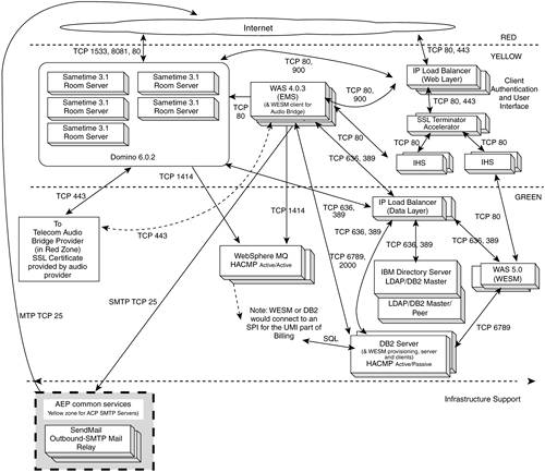
Failover and Load Balancing for Web Conferencing Servers In addition to installation of the application code, the ODW Application Installation Guide describes the configuration and code needed for failover and load balancing: -
AIX Highly Available Cluster Management Program (HACMP) Active/Active configuration for the WebSphere MQ servers. -
HACMP Active/Passive configuration for the DB2 servers. -
LDAP Master/Peer configuration. -
WAS clustering for the EMS and WESM servers. -
HACMP Active/Active configuration for the SMTP servers. Brief Description of Each Web Conferencing Server Type This section briefly describes each of the servers given in Figure 13-6. Sametime 3.1 Room Servers. Sametime 3.1 on Domino 6.02 servers are where the actual Web conferences are conducted . The Room Servers will be shared by multiple customer organizations. Usage data is contained in log files that have no user access. WAS 4.0.3 (EMS). The EMS (Enterprise Meeting Server) server runs on WebSphere Application Server (WAS). EMS is an option with the Lotus Web Conferencing 3.1 (Sametime 3.1) product. EMS is used for meeting management and to load balance meetings across the Sametime 3.1 Room Servers. EMS utilizes the LDAP directory and the DB2 data store. IHS . The IBM HTTP Server systems provide the HTTP user interface. Multiple servers are used for redundancy and horizontal scalability. The EMS and WESM systems each require their own set of IHS servers since EMS and WESM require different levels of WebSphere Application Server. IBM Directory Server (LDAP/DB2) . We will utilize the IBM Directory Server as an LDAP credential store. Multiple servers will be used for redundancy and future horizontal scaling. This server stores information about customer user IDs, passwords, etc. The Directory will be implemented using the IBM Directory Server product (formerly known as Secureway). There will be replicas of the directory for horizontal scalability. The directory is used for user credentials (authentication). WAS 5.0 (WESM) . The WESM (WebSphere Everyplace Subscription Manager) server runs on WebSphere Application Server (WAS). We will utilize WESM to enroll customers, authenticate users, hook to the billing system, etc. WESM utilizes the LDAP directory and the DB2 data store. DB2 Server . Meeting information and log data are stored in the DB2 system. The DB2 server is utilized by both WESM and EMS (with different instances of DB2). The LDAP server will include its own local copy of DB2. The DB2 server also houses the WESM provisioning server and "out of the box" WESM provisioning clients. WebSphere MQ . Messages from the room regarding changes in meeting state (active, scheduled, or finished) and room server availability are passed to EMS via the MQ server. The MQ Server passes health messages regarding the state of a room server (e.g., 20 meetings with 200 users, memory utilization 50 percent, absence of message indicates servers down, and EMS begins failover process). The WebSphere MQ servers use HACMP in active/active mode for failover and some load balancing. SMTP Outbound Mail . The SMTP outbound mail relay servers will initially (Phase 1 of the project) be part of the ODW CORE system. However, for later phases of ODW Web Conferencing, we will use SMTP mail (inbound and outbound) via Application Enablement Program (AEP) common services. ODW Web Conferencing will also make use of other AEP common services as they become available (e.g., LDAP services). |