Section 9.2. Technical Variables
9.2. Technical VariablesYou must consider several technical variables when designing and implementing an RFID solution, including the following:
Several of these variables further consist of subvariables. An optimal RFID solution has to determine a good tradeoff among these variable to arrive at a satisfactory working solution that is within the budget and schedulenot an easy task by any means. This task becomes increasingly challenging with the increase in scale and complexity of the solution. This chapter provides sample templates that you can use to methodically analyze these variables and record your findings. You can customize these templates to suit your particular requirements. You might simplify a template provided here by deleting variables not pertinent to your project. On the other hand, you can enhance a template by adding other custom variables so that the template covers your particular project variables adequately. A template can refer to other templates. For example, the Item ID field of the Tag template refers to the Item ID field of the Item template. A template provided here captures the RFID-specific variables and their subvariables. It does not generally capture other common project-related variables such as personnel, although that is accounted for in the Maintenance template. In addition, you can further normalize a template in the sense that you can extract a set of fields from it and make those into an independent template. For example, Readability fields in the Tag template can be taken out and combined with the Vendor and Test Case templates to create a Readability template. This chapter leaves these and other possibilities to you to explore so that the discussion can focus on RFID-specific variables. The following subsections discuss each of the previously listed variables. 9.2.1. Frequency of OperationFigure 9-4 provides a sample template for this variable. Figure 9-4. Frequency template.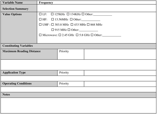 Frequency of operation is by far the most important technical variable in designing an RFID system. Designers should not proceed any further with technical design work until they have determined the exact frequency of operation of a system. Why does frequency play such an important role? The answer is simple: The capabilities of RFID systems vary widely depending on the frequency type. After you know the frequency type, you can methodically tackle all the remaining variables. How can you determine the frequency of a system? The following three primary factors typically enable you to do so:
Before delving into these factors in detail, you need to understand an important nontechnical issue regarding frequency selection: the legal limitations on the frequency that the designers have selected. If a 915 MHz frequency has been selected for an RFID application that needs to be deployed in Europe, for example, you have a problem because this frequency is not a legal European frequency for RFID. You can, however, use the 868 MHz frequency instead. In contrast, if you select a 868 MHz frequency for an RFID application to be deployed in the United States, again you have a problem because this is not considered legal in America. So what can you do if a selected frequency is not legal in the region of deployment? You have the following options:
The first option involves changing the illegal frequency to its closest equivalent that is permissible in the deployment region and at the same time satisfactorily meets all the application requirements. This is probably the easiest to do, assuming, of course, such a permissible frequency is available. Vendors can also provide a working solution to this problem. Several current vendors now have readers that can operate in multiple frequencies, thus bypassing the legal restrictions on frequencies. This option also proves useful if a single RFID application needs to be deployed in different geographical regions and the frequency band is illegal in at least one of the regions. If you need to deploy a UHF frequency application in the United States and Europe, for example, you should select those vendors who can supply RFID hardware that can operate in both 915 MHz and 868 MHz. If you do so, the same application will work in both the places with little or no change, and thus alleviate the implementation and maintenance nightmares associated with creating two different systems that are functionally identical. Some countries grant special licenses for temporary use of a frequency band, even though this frequency might be illegal in that country. However, this approval process might prove time-consuming. If you do pursue this option, allow yourself plenty of lead time. This option proves useful in certain situations, such as if you are planning a pilot study for a temporary period of time to evaluate the technology or validate some assumptions made about certain aspects of the technology. Long-term special license for an illegal frequency might not be easy to obtain unless the RFID application is one of a kind that meets a dire need in some important sectors, such as national defense. The following subsection explores the factors that can determine the right frequency for an RFID application. 9.2.1.1. Maximum Reading DistanceMaximum reading distance is one of the most important factors in determining the frequency of a system. The reading distance generally narrows down the range of possible frequencies to one or a couple, out of which it is relatively easy to determine the best one. For example, for solutions that need close proximity of the tag (from a few inches to less than 3 feet) to the reader, you should use either LF (typically 125 KHz or 134 KHz) or HF (typically 13.56 MHz). Chapter 1 discusses these frequency types in detail. 9.2.1.2. Application TypeIn general, each frequency range is associated with classic applications. For example, for proximity card type applications, LF (typically 125 KHz) is typically used. So if a proximity card type application is being designed, the designer can select the 125 KHz frequency by just matching the application type with its appropriate frequency (see Chapter 4, "Application Areas"). 9.2.1.3. Operating ConditionsSome typical operating conditions can provide a strong hint to the frequency. For example, if the application needs to be less affected by things such as metal, mud, or snow, an LF (typically 125 KHz) or an HF (typically 13.56 MHz) is probably the ideal choice. Also, in hospitals, HF (13.56 MHz) is the typical frequency of choice because it poses minimum interference issues with the existing equipment. The reading distance, generally, is the ultimate deciding factor in frequency selection. Although the application type and operating conditions are helpful, it is the reading distance that finally determines the correct frequency type. What can you do if a frequency selected based on the reading distance differs from the one selected based on other factor(s)? In this case, the factors should be prioritized in terms of importance. The frequency associated with the most important factor should then be selected. For example, one large tire manufacturing company deviated from the Automotive Industry Action Group's B-11 standard for North America to build its application to monitor tire pressure and temperature. The B-11 standard specifies a reading distance of 24 inches and a frequency of 915 MHz. However, the operating conditions distorted the results, and the company decided to use the LF (125 KHz) instead so that its application would be less impacted. 9.2.2. TagsFigure 9-5 provides a sample template for this variable. Figure 9-5. Tag template.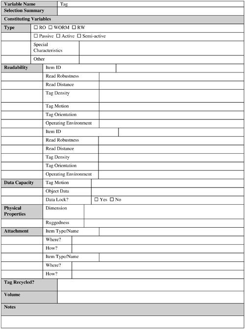 This seemingly simple component involves the following subvariables, virtually all of which you need to considered when designing an RFID system:
Optimizing each of the variables might turn out to be an extremely difficult task, if not an impossible one. You should first attempt to achieve the optimum balance among the variables. If you cannot do so, make an acceptable tradeoff. This is one of the decisions that you should not take lightly or make in haste, because this is the single most important decision that will influence the recurring application cost and the data-collection capabilities of the application. The following subsections examine each these variables. 9.2.2.1. TypeThe type variable refers to the tag type that will be used in the application. The following are some of the major questions that you need to answer in this context:
As you can understand from this list, even a simple-looking decision about tag type involves several variables that you need to carefully consider. 9.2.2.1.1. RO, WORM, or RW?Will the tag already have a unique identifier written onto it by the manufacturer, or is the application going to create the tag when it needs one? Can this tag data be rewritten after it is created? If so, how is data security addressed to make sure that the tag data is not changed unscrupulously by unauthenticated entities? The answers to these questions depend on the type of data that needs to be stored on the tags. If the tag just needs to store a unique static identifier, a RO or a WORM tag is exactly what is needed. If the tag data can change, which means that it contains dynamic data specific to the tagged object (together with a unique static identifier), RW tags are needed. If the application is going to be used inside the four walls of an enterprise with acceptable security in place, then perhaps security is not a great concern. However, you should evaluate this based on the company's auditing capability, shrinkage history, and so on. 9.2.2.1.2. Passive, Active, or Semi-Active?Generally, unless the application needs custom tag featuressuch as sensing the temperature, humidity, and so onthat differ from the basic tag properties of storing and transmitting its data, passive tags might do just fine. However, the RFID system will definitely need active tags if such custom features are required that need on-board processing. In addition, if the application involves high-speed movement of tagged objects, use of semi-active tags is a possibility. 9.2.2.1.3. Special Characteristics?Special characteristics (for example, tags customized for tagging metallic objects or items containing RF-absorbent liquids) might be required depending on the application requirements. This is an important concern. System performance could be seriously degraded if an incorrect tag type is chosen that leads to poor readability when attached to the desired object. Note that a suitable tag for tagging the item in question might not exist! Developing a custom tag for a particular item is generally expensive and typically costs $100,000 or more. 9.2.2.1.4. Other?The tag might have additional properties that are not captured by the previously mentioned subvariables. If EPC tags are used, for example, this subvariable can mean EPC Class0/0+/1 or EPC Gen 2. In addition, if a particular tag type from a vendor is used, it can be associated with this variable together with any vendor-specific product code number. 9.2.2.2. ReadabilityReadability is an extremely important variable associated with a tag, because you want a guarantee that a tag will be successfully read by a reader in the operating environment. Therefore, this element alone can determine the success or failure of an RFID system. To ascertain the readability of a tag, consider the following:
Tag readability varies with the type of the item to be tagged. It is difficult, if not impossible, to theoretically predict the tag readability correctly. Tag readability can only be reliably determined by setting up test RFID systems in the actual operating environment using actual RFID tags, readers, antennas, and the items to be tagged. It is important to do readability testing in the actual operating environment during normal operating hours, so that the testing can properly take into account all the variables that might bear on the readability. Such a setup might prove impossible because of various reasons. In this case, the testing should be done in a setup that mimics the actual operating environment as closely as possible. Even then, it is entirely possible that the readability results from such an environment will differ from the readability realized in the actual operating environment. Today, several vendors and integrators have set up their own RFID labs where they can perform readability testing on behalf of a business. 9.2.2.3. Data CapacityData capacity is a crucial variable that can have a great impact on application aspects such as cost and efficiency. The main questions that you need to ask here are as follows:
The answer to the first question depends on whether the tag data is "license plate" type or contains other information, such as tagged object attributes. In the first case, most probably a 96-bit EPC Class 0+/1 or even a Class 0 tag might be fine. Why might? Because a designer might want to use a non-EPC type unique identifier, for example, which can be longer than a 96-bit EPC code. This practice is not totally uncommon in today's applications. In this case, the unique identifier actually encodes some object-specific data such as the expiry date, batch number, and so forth in it. Thus, it serves two purposes: First, the unique identifier is used to uniquely identify the item; second, a customer or operations personnel can use the same identifier to get some fundamental information about the item without having to access the enterprise product database. At the same time, the identifier is not so large (this is typically kept under 128 bits) so as to cause concern about the errors and delays associated with read transmission and write operations. If some specific tagged object information needs to be stored on the tag together with its unique identifier, a larger memory size is needed. Some examples of such tagged object data are its part number, maintenance history, and so on. It is not uncommon to use tags whose memory size is larger than 256 bits, and prototypical systems have successfully used tags with as many as 40,000 bits. You might need data locks to prevent tampering with the tag data. You can lock a portion of the tag data so that it cannot be modified. A data lock can either be at the hardware level or at the software level. For Class 0 EPC tags, the unique identifier is burned onto the tag itself and hence is permanently locked from being changed. In contrast, a software lock (for example, for Class 1 EPC tags) can use a password scheme to unlock the locked data segments. 9.2.2.4. Physical PropertiesThis is another important variable that you should consider when designing an RFID system. Major concerns regarding physical properties include the following:
A tag should never be hacked by unwary individuals to bring the tag's physical dimensions down to an acceptable size for tagging an item. This includes folding the tag, cutting it using a pair of scissors, and so forth, which can seriously detune the tag antennas. If someone does so, modified tag might fail to draw sufficient power from the reader antenna signals, resulting in partial or total failure to transmit its data. Note that it is not uncommon to physically modify a tag (for example, drill holes into the tag antennas to increase its readability)! However, this should only be attempted by appropriate persons (such as the tag designers, for example) who know what they are doing. 9.2.2.5. AttachmentThe way a tag is attached to an object plays an important role in the proper reading of the tag. This also varies with the item type. The following two questions must be answered in this regard:
It is difficult to theoretically answer both of these questions. Experimentation is necessary in a test setup with the actual objects to be tagged and appropriate RFID hardware. Also, it is desirable that this activity be performed in the actual operating environment during normal operating hours so as to correctly factor in the variables that can affect the readability of the tag. This activity can be done in conjunction with the tag readability evaluation. 9.2.2.5.1. Where Is the Tag Going to Be Attached?The tag should be attached to the object so that it does not hide important information, such as product brand and so forth, on the product packaging. Therefore, there may be only specific areas on the product packaging where the tag can be placed. It is important to identify these areas early in the design phase. A good rule of thumb is to place the tag next to the UPC label of the tagged object, where operations personnel can easily locate it. If it is determined that a tag cannot be satisfactorily placed anywhere on an item packaging, the packaging layout might have to be changed! Although this might seem a little too extreme, remember that designing an RFID application is a two-way street. Therefore, the business cannot expect benefits from the technology without providing some flexibility of its own. In general, you should not attach a tag on crush or fold points (where it would be prone to damage). 9.2.2.5.2. How Is a Tag Going to Be Attached?Generally, if the product is made of RF-lucent material, a simple adhesive back strip is sufficient to mount the tag on the desired object. The situation is complicated when the tagged object material is made of RF-opaque or RF-absorbent material. In these cases, a spacer made of some type of RF-friendly material, such as a foam board of a certain thickness, can be used to mount the tag on the object. The thickness of such a spacer is typically equal or proportional to one quarter of the frequency wavelength used. This generally works for objects made of metals or objects that contain RF-absorbent liquids. In case of metals, you can physically attach the tag antenna with the metal portion of the object to increase the effective tag dimensions. A tag can also be attached so that a part of it extends out of the item's metal portion. In case of liquids, you can use multiple reader antennas so that the resulting strength of the RF-signal reaching the tag is sufficient to energize it in spite of getting attenuated to some degree. (This means that the readers are transmitting synchronously and in-phase.) 9.2.2.6. VolumeThe volume variable is concerned with how many tags need to be used to tag the objects in the application for a particular period of time (a year, for instance). If tags are recycled, this number can be reduced substantially. If tags are not recycled, this will be a recurring overhead to operate the RFID application. When ordering tags, take care to order sufficient spares (depending on the error rate of tag creation as well as damaged tags). Currently, faulty tag rates can be as high as 20 percent or more! 9.2.3. ReadersFigure 9-6 provides a sample reader template. Figure 9-6. Reader template.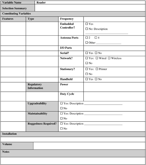 This variable is further composed of the following subvariables:
A reader occupies the central position from the perspective of data collection. Therefore, much of the system's data-collection capabilities directly depend on the readers used. The new breed of readers provide sophisticated features such as SNMP (Simple Network Management Protocol) for real-time monitoring and management in a networked environment, data aggregation, and so on, which underlines the central role played by the readers in an RFID system. The following subsections discuss each of these subvariables. 9.2.3.1. FeaturesThe following main factors are to be considered in this context:
As you can understand from this list, you must consider several reader factors so that it can successfully meet the application requirements. 9.2.3.1.1. TypeFirst, the reader has to operate on the selected frequency. If more than one frequency type is needed (for deployment in different geographical regions with varying frequency restrictions), it would be perfect if the reader can support these in the form of a multiple-frequency reader. Second, the reader needs to support at least two antenna ports (although four ports is becoming the norm). It is generally a safe bet to use a four-port reader because these offer better read zone coverage without a substantial price difference compared to a two-port reader. Third, the reader might need to support the number and type of I/O ports needed by the application. If a suitable controller is used that can provide these I/O ports, this is not required from the reader. Fourth, the reader controller is needed to support interfaces for sending tag data sets, I/O control, monitoring, and management. A controller is generally offered as a part of standard feature sets of almost any reader available today. However, depending on the application requirements, some specialization of these features might be necessary (such as support for a particular I/O port type for a particular I/O device [for example, a motion sensor]). However, such a reader might not even exist. Fifth, does the application require serial readers or network readers? Serial readers are not susceptible to network failure because they connect to the host computers over a serial connection. In contrast, network readers are flexible to configure as network devices, leading to better remote management, and they typically do not need as many host computers as needed by the serial readers. Sixth, the application might require stationary or handheld readers. Handheld reader area is currently undergoing rapid improvements. Therefore, a handheld reader matching your application requirements today might not be available yet. Take proper care when using a handheld reader to read a single tag. If more than one tag is present in the vicinity, a handheld reader might read several tags at once, including the tag of interest. This situation can also happen with stationary readers. For stationary readers, you can alleviate issue by using attenuators (see Chapter 1). Although the wired readers are most frequently used, depending on the application requirements the reader might need to be wireless. The wireless requirement is generally targeted to a handheld reader. 9.2.3.1.2. Legal RestrictionsMost countries have legal restrictions on the transmitter power and duty cycle of a reader (see Chapter 1). Therefore, you need to confirm compliance of your selected reader type(s) with these limitations. Also, a reader's transmit cycle power should not be increased (decreasing it is fine) without express permission from regulatory bodies. Therefore, you should not tamper with a reader that is already certified as compliant with the legal restrictions. Doing so might violate the regulatory body license(s) and void the reader warranty. 9.2.3.1.3. UpgradeabilityTo maximize your hardware investment, a reader's firmware should be upgradeable for future enhancements and for fixing existing bugs in the current firmware. This can lead to a considerable amount of cost savings when the existing application is upgraded or maintained at its current capabilities. It is strongly recommended that any reader, either stationary or handheld, selected for an application should be upgradeable. The capability of remotely upgrading a reader is preferable so that upgrades can be performed centrally in an optimized manner. A centralized upgrade eliminates the personnel time required to visit the installation site and manually upgrade each reader in turn. 9.2.3.1.4. ManageabilityYou want a reader that you can manage remotely so that you can centralize and automate monitoring and management of reader's health. In case of a reader malfunction, you can remotely (and efficiently) track, diagnose, and fix the error. With such readers, you have minimum need for any service personnel to visit the installation site and prolong the operation downtime. 9.2.3.1.5. RuggednessGenerally, a reader is not built as a rugged device. Depending on the requirements, however, a reader can be ruggedized. For example, a stationary reader can be enclosed in a rugged housing to prevent it from being affected by extreme cold, shock, vibration, and so on. A reader vendor can customize a reader to meet specific ruggedness requirements. 9.2.3.2. InstallationAlthough selecting the right reader is important, proper installation of it also requires good deal of attention, despite its mundane nature. Proper installation of a reader might require additional structures such as a portal to be built at the read zone. The reader and its cables cannot dangle in a manner such that it poses a risk to the operations personnel. Also, a reader might need to be fine-tuned (for example, by attaching in-line attenuators to the antenna ports to focus its transmitted energy in a smaller area and minimize interference). Long cable extensions connecting a reader with an antenna attenuate reader signals. Therefore, if the distance between the reader and the antenna is more than 6 feet (approximately 2 meters), you might need to use a high-quality low-loss cable. However, these types of cables are expensive and could increase the installation cost. The physical layout of the environment surrounding the reader antennas can also require a significant amount of installation effort. In short, proper installation of readers represents a nontrivial task that needs to be handled by qualified professionals. 9.2.3.3. VolumeThis variable deals with determining the number of readers the application needs. This number depends on the number of read zones in the application, the number of readers needed to adequately cover each read zone, and the number of antenna ports supported by a reader. In general, the number of readers needed, each with four antenna ports, will be less than the number of readers needed if they have two antenna ports each. However, this can be complicated by the fact that a particular read zone setup might be such that only two antennas can be used per reader to avoid reader interference. Spare readers need to be considered as well to prevent operations interruption in case of a reader failure. 9.2.4. AntennasFigure 9-7 provides the sample template for the antenna variable. Figure 9-7. Antenna template.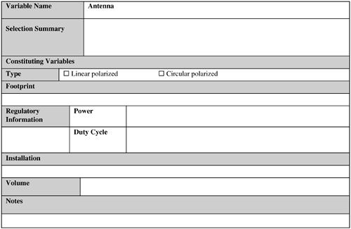 This is another significant variable when you are designing and implementing an RFID system. This variable consists of the following subvariables:
These are among the simpler variable types and are relatively easy to tackle. This variable is easier to deal with because of the limited options available with regard to reader antennas in terms of features and complexity. 9.2.4.1. TypeYou might recall from Chapter 1 that there are two types of antenna: circular polarized and linear polarized, if UHF is used. If the application requires that tags can be arbitrarily oriented to the antenna, you should use a circular polarization antenna. If a longer read range is desired or if the tag orientation to the antenna is fixed, you should use a linear antenna used. Antennas are generally not rugged, but can be ruggedized by the vendor. 9.2.4.2. FootprintThe antenna footprint, as discussed in Chapter 1, is a three-dimensional region consisting of RF waves emanating from the reader. A tag, when placed inside this region, can be read by the reader attached to the antenna. In reality, antenna footprint shape is rarely symmetrical because it is affected by RF interference in the operating environment. To determine the actual footprint map precisely, you need specialized equipment such as a spectrum analyzer or network analyzer. The hardware vendor or hardware services consulting companies can help with mapping the antenna footprints at the operations site. 9.2.4.3. Power and Duty CycleAs detailed in Chapter 1, reader antenna power and duty cycle are constrained by regulatory bodies. Antenna power and duty cycle cannot be increased without express permission from the appropriate authorities, but you can always decrease it (useful in the case of antenna power if you need to limit the read distance). A decrease might prevent the RFID system from interfering with any neighboring RFID systems or reading tags that are out of range (for example, in an access control type of application). Power reduction can seriously affect the antenna footprint. 9.2.4.4. InstallationYou should install an antenna as close to tags as possible and as far away from metals as possible (in UHF and microwave) to reduce reflection. FCC requirements for installing reader antennas states that an antenna should be positioned in such a manner that the personnel in the area for prolonged periods may safely remain at least 9 inches (about 23 centimeters) in an uncontrolled environment from the antenna's surface.[1] Antennas attached to different readers can cause reader interference when their read zones overlap. Therefore, you must take care to avoid this issue. Antennas might need to be installed in various positions to maximize the tag readability (for example, on the sides of dock doors, below a moving conveyor, above a canopy). You might have to construct specialized structures for this purpose. To maximize overall coverage area, you might have to tilt an antenna or install it at a particular height. Such tweaking depends on factors specific to where the antenna needs to be installed (such as dock door dimensions and so forth).
Consider the following regarding antenna installation:
The last three variables have already been discussed. The following subsections discuss the first two variables. 9.2.4.4.1. InterferenceThis includes reader interference, which has already been discussed. Also, to avoid human interference issues, you might need to install antennas at particular vantage points in the read zone. Some older wireless LANs in the 900 MHz range can interfere with the readers. You can mitigate the interference to some extent by placing reflectors (such as sheets of Mylar) in the packaging to help bounce the RF signal to the reader. Interference is also discussed in Section 9.2.6, "Operating Conditions." 9.2.4.5. Tag LocationYou must determine the coordinates (position and height) of where a tag is going to be located in the read zone to determine where to mount antennas. If the tag location range is large, you will probably need multiple antennas to read all the tags in the read zone. You might need to mount antennas on the sides and on the top and or the bottom of the read zone. To attain longer read ranges, you should use linear polarized antennas. 9.2.4.6. VolumeThe number of antennas needed for an RFID application depends on the number of read zones supported by this application and the number of antennas needed to cover each read zone adequately. Think about spare antennas when determining how many antennas you need. Spares will help prevent operations impact in case of an antenna failure. 9.2.5. Items to be TaggedFigure 9-8 provides a template for this variable. Figure 9-8. Item template.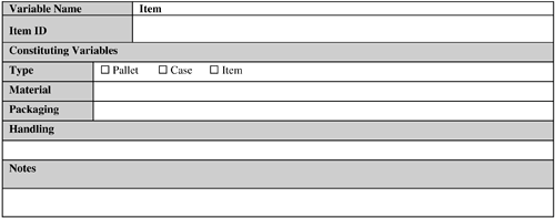 The importance of this variable cannot be overstated. In short, how well the items of an RFID application can be tagged plays a significant role in determining its success or failure. The following factors need close attention from the designers:
The last two factors have already been discussed previously in this chapter. The following subsections analyze the impact of the remaining subvariables on an RFID application design. 9.2.5.1. TypeThe item types can be broadly divided into the following three categories:
Note that depending on the reading requirements, the relative degree of difficulty in reading a pallet, case, and individual product can vary. 9.2.5.2. MaterialIf the item is made of RF-lucent material for the frequency used (such as paper, dry wood, certain types of plastics, and so on), tagging such an item is much easier compared to situations where the item material type is RF-opaque (metals) or RF-absorbent (water, shampoo, and so forth). 9.2.5.3. PackagingPackaging material plays an important role in determining tag readability of an item. If the packaging material contains metal foil, conductive carbon, or graphite, it might become difficult to properly read the tag attached to this packaging type. Also, a packaging material might absorb moisture to such an extent that it might act as an RF-absorbent material, leading to low tag readability. In these cases, the manufacturer might need to change the packaging material to strike a balance between the product advertisement needs and proper tag readability. If an item consists of multiple constituent objects (for instance, an eight AA battery pack), tag readability of this item might also depend on how densely the individual constituent objects are packed inside this item. In addition, for case-level tagging on a pallet, if the cases are packed too deep (depending on the case size and the packing depth), the case tags located near the center of the pallet might not be read at all (or with great difficulty), even assuming the use of an optimally tuned RFID system (irrespective of whether the material type of the case is RF-friendly). The reason is that the RF energy can penetrate only up to a certain depth, even in the case of RF-friendly material, depending on the output power and duty cycle of the readers. If an RFID tag is located at or below this depth, the RF energy will not be able to reach this tag. As a result, this tag cannot be read. Also, if pallet cases are small and densely packed, the antennas of some of these tags might couple the antennas of other tags (for example, by physically touching one another). (Note that this is frequency dependent and antennas do not have to physically touch each other to couple and detune.) As a result, these tags cannot draw power from the reader antenna and hence cannot be read. This is known as the shadowing effect. The items should be packed so that the shadowing effect is minimized. 9.2.5.4. HandlingThe methods and equipment used for handling a tagged object can impact tag readability. For example, if forklifts are used, the metal forks and the chain-lift assembly can reflect and prevent RF waves from reaching the tags, which are located closest to these handling parts. In addition, the wireless communication devices used by forklift operators might cause RF interference and impact readability. Last but not the least, the speed at which the forklift is moving can also affect readability. The effect of speed on readability has already been discussed. Similarly, for any other equipment type, the presence of metal, RF interference, mechanical vibration, electrostatic discharge (ESD), and motion can all impact tag readability. 9.2.6. Operating ConditionsFigure 9-9 provides a sample template for operating conditions. Figure 9-9. Operating Conditions template.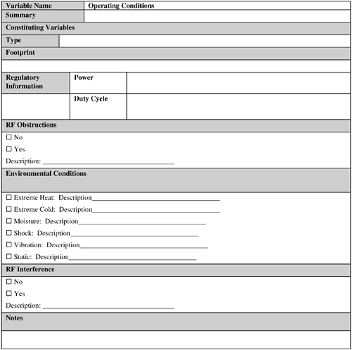 No two operating conditions are identical, even if they seem so. Operating conditions are like a person's fingerprinteven if two individuals look eerily similar, their fingerprints will not. Operating conditions can have a substantial bearing on the proper working of any RFID application. These conditions can be broadly classified as follows:
It is difficult if not impossible to theoretically determine the impact of these variables. An RFID system needs to be tested at the actual operating site during normal operating time to determine the sum total impact of all the environmental condition variables on the system. Remember that a high-performance RFID solution designed for a particular business's operating conditions might perform poorly in its customers', distributors', or trading partners' operating environment. Therefore, designers and implementers need to consider these operating conditions when developing such an RFID application. 9.2.6.1. RF ObstructionsRF obstructions might result from the presence of RF-opaque objects and mobile equipment that effectively blocks RF waves from reader antennas reaching the tags. In addition, there could be RF-opaque objects, such as metal, in the environment that reflect the RF waves with similar impact. Finally, the environment might also contain dampeners or attenuators, such as people, RF-absorbent liquids, and construction materials, that can weaken the RF waves considerably, leading to read failures. In fact, the presence of human traffic is probably a certainty in any operating environment and can present a substantial challenge to overcome. The impact of these factors varies with the frequency used. The effect of these factors is most pronounced in UHF and microwave frequencies, and least in the LF and HF. 9.2.6.2. Environmental ConditionsEnvironment conditions include the presence of static, moisture, extreme heat or cold, shock, and vibration, all of which can affect the proper working of tags and shorten the life of tags, readers, and antennas. In addition, the presence of a substantial amount of moisture in the environment can dampen RF signals, resulting in insufficient energy reaching the tags for initiating data transfer. As a result, invalid reads and read failures might occur. 9.2.6.3. RF InterferenceAn existing installation base of RFID systems, which might or might not use the same frequency and type (for example, backscatter or transmitter) as the target system, might interfere with the latter. In addition, RF devices such as wireless radios, Wi-Fi, and Bluetooth can significantly contribute to the interference problem, too. Also, conveyor motors and controllers can generate RF noise that can interfere with the RFID system (but not to a substantial degree). 9.2.7. VendorsFigure 9-10 provides a sample template for capturing vendor details. Figure 9-11 provides an example test case template. Figure 9-10. Vendor template.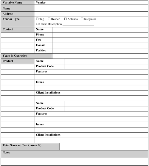 Figure 9-11. Test Case template.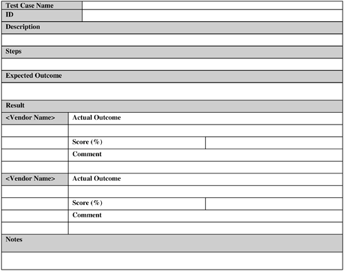 The data-collection capabilities of an RFID system is as good as the RFID hardware (that is, the tags, antennas, and readers), the RFID software used by the system, and how these components are tied together by the integrator(s). For example, although the RFID hardware currently offered by vendors is largely comparable, some vendors can offer specific hardware features that almost perfectly match the requirements of the RFID application under consideration. Therefore, selecting the right vendor(s) can be a crucial part of the application design and determine the degree of success of the system. Keep in mind the following factors when selecting system vendor(s):
Vendor selection activity can commence as soon as the application (functional and nonfunctional) requirements are finalized. Vendor selection should not be done in haste. The test cases for evaluating the vendors should be carefully crafted based on actual application requirements. Then the vendors should be invited to participate in the evaluation effort (or a test lab can do this on behalf of the business using different vendor hardware). Vendors should then be evaluated and ranked based on how they fared on the test cases. The top three vendors may now be considered as potential candidates and can further be narrowed down based on their references, financial stability, and so forth. This entire effort from designing test cases to the selection of the winning vendor can easily take weeks. So this activity needs to be planned ahead and executed as early as possible in the design phase. The following subsections discuss each of these variables. 9.2.7.1. Use Actual EvaluationVendor selection should be based on actual evaluation results. It is not prudent to select a vendor based on its hardware or software literature and data from case studies and "reference cases." Just because the hardware or the software worked for another application, which might even be similar, you have no guarantee that it will work for the application in question. The actual evaluation of the hardware using pertinent test cases should be performed, most preferably at the actual operation site, during normal operating hours. The vendor(s) should be able to prove that their hardware really works for the actual items under the actual operating conditions. 9.2.7.2. Avoid Vendor Lock-InOne of the best strategies to bypass vendor lock-in is to avoid proprietary solutions from a vendor and base the RFID application design on a well-supported standard. Hardware and software from the different vendors that support a particular standard have a higher chance of being compatible with each other than the proprietary solutions from these vendors. 9.2.7.3. Select Multiple VendorsIf you cannot find a single vendor that can perform end-to-end implementation, it is fine to select multiple vendors, some of which might supply the tags, some the readers and antennas, and the remaining ones the software and integrating service. However, the hardware and software should be compatible with each other so that the application can be implemented by integrating these components together. The best way to guarantee this is to base the application design on a well-supported standard and use the compatible components from the vendors. 9.2.7.4. Plan for UpgradeRFID technology is undergoing rapid changes, and vendors are bringing out new hardware, firmware, and software upgrades at a furious rate. To prevent hardware and software obsolescence and continuous upgrading effort, designers need to come up with an upgrade strategy. This strategy can include items such as using backward-compatible hardware and software from the vendors, defining minimum upgrade intervals, ability to upgrade existing reader firmware, and so forth. However, at present, upgrading to new hardware seems like an unavoidable option. So this must be planned for properly in advance. 9.2.7.5. Vendor SupportIf a vendor cannot support its hardware or software in a timely fashion in the deployment region(s), it is debatable whether it can be a preferred vendor. Never assume, for any reason, that support at any point is unnecessary. On the contrary, support is always a necessity from the hardware, as well as from software and possibly from services, perspective and should be built in to the plan accordingly. 9.2.7.6. Vendor RelationshipThe importance of having a good vendor relationship can hardly be overstated. This might not seem obvious at first. After all, doesn't a vendor relationship end with the timely delivery and maintenance of its products? Not really. As RFID technology is maturing, the vendor products are also changing at a rapid pace. The business should take this opportunity to provide the vendor with guidance to improve its product line. For example, the business can use the results from its RFID pilot to report issues with tag readability and the conditions under which it is happening. This information will allow the vendor to rectify the issues and present the business an improved version of its product. This symbiosis will benefit the business, the vendor, and the RFID technology in the long run. Also, if special feature support is required by a business application but is currently missing, the vendor can deliver a prototype version of its hardware that includes this feature. This prototype will allow the business to meet its delivery timeline without the need for the vendor to upgrade its product line overnight (sacrificing its delivery and quality assurance processes). This type of cooperation is greatly facilitated by a good relationship between the business and its vendor. Therefore, a vendor should not be treated as an adversary, but as a partner with whom the business vision should be shared. After all, you want the vendor to understand and anticipate the business needs and align its products accordingly. 9.2.7.7. Plan for ContingencyWhat happens if there are issues with the selected RFID vendor down the road? Among other things, a vendor might not be able to supply the hardware or software on time, balk at the maintenance promises, go bankrupt, encounter patent-infringement lawsuits (and can then go bankrupt as a result), or simply decide that it might not want to play in the RFID arena anymore. Designers need to have a contingency plan to address these issues. Again, if the design is based on a widely accepted standard, you might be able to replace one vendor's products with those from another vendor (that also supports the selected standard) without causing a major catastrophe in the application delivery. 9.2.8. StandardsFigure 9-12 provides an example Standards template. Figure 9-12. Standards template.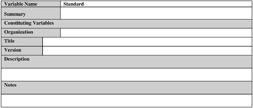 Any RFID application design should be based on a standard for the following reasons:
These are critical success factors for an RFID system (or any system, for that matter) in the long run. It is tempting to craft a proprietary system in the haste of pushing out the first version of an RFID application in the field. This is especially true for a closed-loop system for which there is no need to share the data with outside world. Although such an effort might be successful in the short run, the chances are high that it will run into a number of issues in the long run, particularly when the need to share data with external entities arises. Therefore, the recommendation is to resist such a temptation and invest some time upfront to investigate whether a suitable standard exists that can be leveraged for the solution. The following subsections discuss these advantages of standardization. 9.2.8.1. Savings of Time and EffortA standard typically provides a ready-made solution for a set of business problems. By basing the solution design on a standard, the designer is saving himself the time and effort associated with a long and often frustrating effort of building such a solution from scratch. Indeed, if a proprietary solution is used, the designers must provide good reasons for foregoing a standard-based solution. 9.2.8.2. CollaborationAn RFID system has to be compatible not only with the internal systems of the business that has implemented it, but also with external systems such as the systems of suppliers, customers, and business partners. The maximum potential of an RFID solution is usually realized by collaborating with these external entities, not with the entities bound within the four walls of an enterprise. A proprietary solution might have a limited prospect of success regarding compatibility with these third-party independent systems. However, a system based on standards offers the best solution to achieve this goal. 9.2.8.3. ScalabilityScalability is an important aspect of virtually any system that can grow with the business needs. A standard-based solution offers the best prospect for scalability because this aspect is typically built in to the standard itself. However, for a custom solution, scalability might be difficult to achieve because of shortcomings in the solution that were not apparent in the early phases. 9.2.8.4. Freedom of ChoiceIf a standard-based solution is used, the solution components can be mixed and matched from different vendors that support the standard. As a result, the business is not locked-in to any particular vendor. This flexibility is desirable for a technology such as RFID, which is currently dominated by small players. Such a company might not be able to survive unfortunate events such as a legal suit bought by a competitor and so on. It is the designer's responsibility to take these issues into consideration and insulate the business and the application from such impacts. In contrast, a proprietary solution has a good chance to become dependent on a single vendor or a handful of vendors. 9.2.9. Application Software and HardwareFigures 9-13 and 9-14 provide sample Software and Hardware templates, respectively. Figure 9-13. Software template.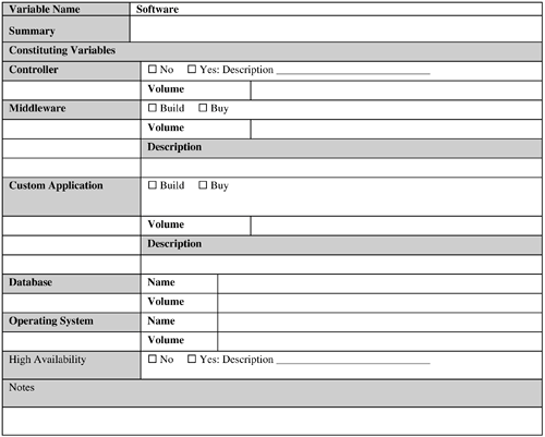 Figure 9-14. Hardware template.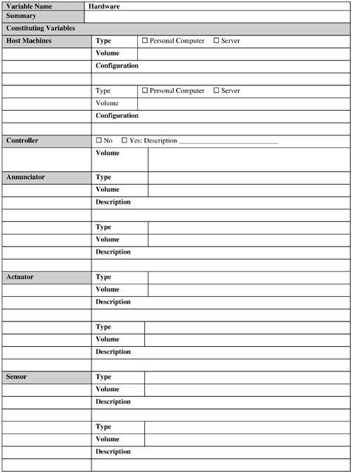 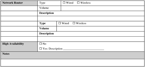 Most of the general practices used for application software and hardware design hold for designing an RFID application, too. Effort should be made to determine whether any existing hardware and software assets can be reused to implement and deploy the RFID system. The following issues should be addressed, at a minimum, in this context:
The following subsections discuss these factors. 9.2.9.1. Data VolumeMassive amounts of data are typically generated by a nontrivial RFID system. This is partly because, unlike bar code, a tag is read multiple times when it is in the read window of a reader. This data needs to be filtered, aggregated to bring it down to a manageable amount when it can be persisted, and used. The RFID middleware should be responsible for handling this aspect. Hence, this software component plays a crucial role in data movement and management. 9.2.9.2. Software Build Versus BuyThis is a classic issue in any application design decision. The software component includes the RFID middleware and application-specific systems such as a fleet management system that the business might not currently own. If the design is based on a standard for which off-the-shelf implementations are available from various software vendors, it can be advantageous to buy this component, especially if the business does not have the appropriate in-house IT expertise and experience to develop this application and has tight resource and time constraints to develop and deploy this application. 9.2.9.3. High Availability (HA) RequirementsThis option almost always will increase the implementation cost. If continuous availability is required, then besides additional hardware, the application/vendor software has to provide built-in support so that the database engine is available for transactions 100 percent of the time. This means two identical but fully independent systems are required, both in terms of software and hardware. The application software has to be aware of these two systems and treat every transaction as being distributed across the two systems. In short, this type of HA solution is the most complex and expensive and should be used for only the most critical systems. Fortunately, most of the RFID applications can use other types of HA. For example, the database engine, middleware, network adaptors, and so on can be tightly integrated with specialized HA software to produce what is known as an HA cluster. This can be configured in different ways. For example, in a mutual takeover option, each machine in the cluster is active and ready to take over in case of a failure; whereas in hot standby, the secondary machines are idle waiting for a failover. This is the next-most expensive solution after continuous availability. The cheapest failover solution involves data replication, which also offers the most limited form of failover. In this case, a standby system is used to back up data from the primary system. In case of failure, manual intervention is necessary to start the standby system to take over the responsibilities of the primary. 9.2.9.4. VolumeVolume is concerned with the quantitative details, such as the number of software licenses, annunciators, actuators, hardware servers, network routers, and so forth, needed to install and run the RFID application at the desired operating locations. With the exception of licensing and ongoing maintenance costs, this is generally a one-time cost. 9.2.10. Integration with Existing SystemsFigure 9-15 provides a sample Integration template. Figure 9-15. Integration template.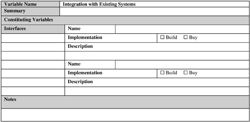 Integration of an RFID application with existing systems might not be needed if the business does not have such existing systems; even when it does, the need for integration might not be desperate. The latter is especially true in RFID trials and pilots used for technology evaluation and business case validations. Also, if a company is just trying to design a slap-and-ship application (see Chapter 8, "Creating Business Justification for RFID") to achieve some sort of RFID compliance for its customers, it might want a bare-bones standalone RFID system with little or no integration with its existing business systems. This is so that the compliance is achieved while spending as few resources and impacting as few aspects of the operations as possible. In the long run, this practice should be avoided. An RFID system is a data-collection system; so if a business spends money to collect data but does not use it to its advantage, it is questionable how much benefit it is getting out of it. To realize the full potential of RFID, the enterprise should, at some point, be prepared to integrate the RFID application with its business processes and back-end system(s). Some large enterprise systems (for example, ERP [enterprise resource planning] and WMS [warehouse management systems]) have already been RFID-enabled by their vendors. The business can look into using this capability if it is using one of these systems. As a general guideline, if a custom interface needs to be developed, the temptation to implement the back-end functionality in the RFID middleware should be resisted. However, the business rules for data filtering and aggregation should be implemented at the middleware level because this is one of the principal functionalities of RFID middleware. But then the business-specific logic for using this processed data (that is, the business transactions) should be implemented at the back end. It is perfectly fine to trigger business transactions from the middleware and at interface levels, but implementing the business transaction at either of these levels is not. The latter implementation types might not scale and can cause synchronization issues in the long run with the back end in terms of logic and data (a maintenance nightmare). 9.2.11. MaintenanceFigure 9-16 provides a sample Maintenance template. Figure 9-16. Maintenance template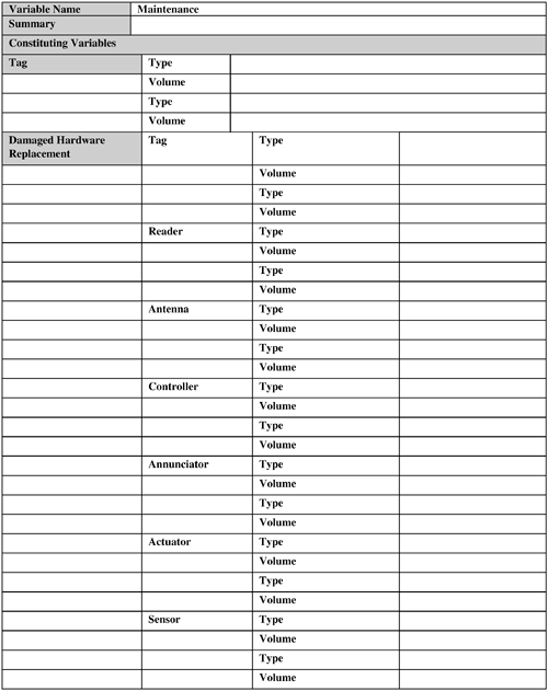 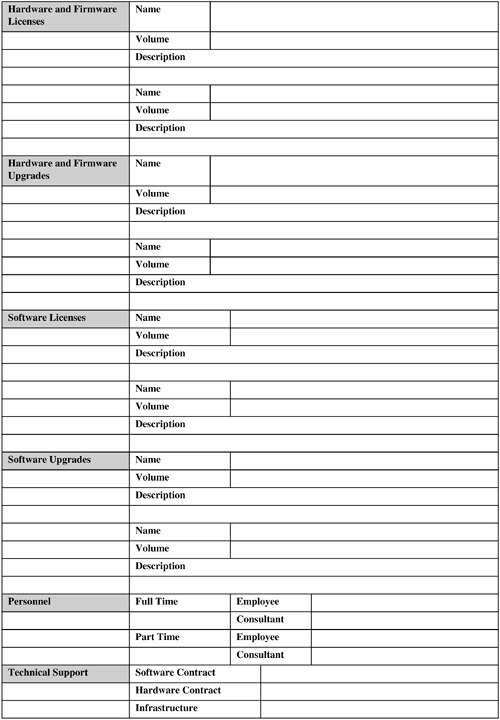  The maintenance activities and the required resources need to be planned in advance, not after the system has been delivered. A major part of TCO of an RFID system actually may lie in maintaining it. You can use the following as a checklist for determining maintenance parameters:
Some of these items, especially the cost of enhancements, can be hard to estimate accurately at design time. |
EAN: 2147483647
Pages: 100