How Client Computers Access LVS-DR Cluster Services
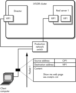
Let's examine the TCP network communication that takes place between a client computer and the cluster. As with the LVS-NAT cluster network communication described in Chapter 12, the LVS-DR TCP communication starts when the client computer sends a request for a service running on the cluster, as shown in Figure 13-1.[2]

Figure 13-1: In packet 1 the client sends a request to the LVS-DR cluster
The first packet, shown in Figure 13-1, is sent from the client computer to the VIP address. Its data payload is an HTTP request for a web page.
| Note | An LVS-DR cluster, like an LVS-NAT cluster, can use multiple virtual IP (VIP) addresses, so we'll number them for the sake of clarity. |
Before we focus on the packet exchange, there are a couple of things to note about Figure 13-1. The first is that the network interface card (NIC) the Director uses for network communication (the box labeled VIP1 connected to the Director in Figure 13-1) is connected to the same physical network that is used by the cluster node and the client computer. The VIP the RIP and the CIP, in other words, are all on the same physical network (the same network segment or VLAN).
| Note | You can have multiple NICs on the Director to connect the Director to multiple VLANs. |
The second is that VIP1 is shown in two places in Figure 13-1: it is in a box representing the NIC that connects the Director to the network, and it is in a box that is inside of real server 1. The box inside of real server 1 represents an IP address that has been placed on the loopback device on real server 1. (Recall that a loopback device is a logical network device used by all networked computers to deliver packets locally.) Network packets[3] that are routed inside the kernel on real server 1 with a destination address of VIP1 will be sent to the loopback device on real server 1—in other words, any packets found inside the kernel on real server 1 with a destination address of VIP1 will be delivered to the daemons running locally on real server 1. (We'll see how packets that have a destination address of VIP1 end up inside the kernel on real server 1 shortly.)
Now let's look at the packet depicted in Figure 13-1. This packet was created by the client computer and sent to the Director. A technical detail not shown in the figure is the lower-level destination MAC address inside this packet. It is set to the MAC address of the Director's NIC that has VIP1 associated with it, and the client computer discovered this MAC address using the Address Resolution Protocol (ARP).
An ARP broadcast from the client computer asked, "Who owns VIP1?" and the Director replied to the broadcast using its MAC address and said that it was the owner. The client computer then constructed the first packet of the network conversation and inserted the proper destination MAC address to send the packet to the Director. (We'll examine a broadcast ARP request and see how they can create problems in an LVS-DR cluster environment later in this chapter.)
| Note | When the cluster is connected to the Internet, and the client computer is connected to the cluster over the Internet, the client computer will not send an ARP broadcast to locate the MAC address of the VIP. Instead, when the client computer wants to connect to the cluster, it sends packet 1 over the Internet, and when the packet arrives at the router that connects the cluster to the Internet, the router sends the ARP broadcast to find the correct MAC address to use. |
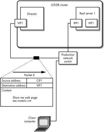
When packet 1 arrives at the Director, the Director forwards the packet to the real server, leaving the source and destination addresses unchanged, as shown in Figure 13-2. Only the MAC address is changed from the Director's MAC address to the real server's (RIP) MAC address.

Figure 13-2: In packet 2 the Director forwards the client computer's request to a cluster node
Notice in Figure 13-2 that the source and destination IP address have not changed in packet 2: CIP1 is still the source address, and VIP1 is still the destination address. The Director, however, has changed the destination MAC address of the packet to that of the NIC on real server 1 in order to send the packet into the kernel on real server 1 (though the MAC addresses aren't shown in the figure). When the packet reaches real server 1, the packet is routed to the loopback device, because that's where the routing table inside the kernel on real server 1 is configured to send it. (In Figure 13-2, the box inside of real server 1 with the VIP1 address in it depicts the VIP1 address on the loopback device.) The packet is then received by a daemon running locally on real server 1 listening on VIP1, and that daemon knows what to do with the packet—the daemon is the Apache HTTPd web server in this case.
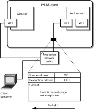
The HTTPd daemon then prepares a reply packet and sends it back out through the RIP1 interface with the source address set to VIP1, as shown in Figure 13-3.

Figure 13-3: In packet 3 the cluster node sends a reply back through the Director
The packet shown in Figure 13-3 does not go back through the Director, because the real servers do not use the Director as their default gateway in an LVS-DR cluster. Packet 3 is sent directly back to the client computer (hence the name direct routing). Also notice that the source address is VIP1, which real server 1 took from the destination address it found in the inbound packet (packet 2).
Notice the following points about this exchange of packets:
-
The Director must receive all the inbound packets destined for the cluster.
-
The Director only receives inbound cluster communications (requests for services from client computers).
-
Real servers, the Director, and client computers can all share the same network segment.
-
The real servers use the router on the production network as their default gateway (unless you are using the LVS martian patch on your Director). If client computers will always be on the same network segment as the cluster nodes, you do not need to configure a default gateway for the real servers.[4]
[2]We are ignoring the lower-level TCP connection request (the TCP handshake) in this discussion for the sake of simplicity.
[3]When the kernel holds a packet in memory it places the kernel into an area of memory that is references with a pointer called a socket buffer or sk_buff, so, to be completely accurate in this discussion I should use the term sk_buff instead of packet every time I mention a packet inside the director.
[4]This, however, would be an unusual configuration, because real servers will likely need to access both an email server and a DNS server residing on a different network segment.
EAN: 2147483647
Pages: 219