Chapter 12: The LVS-NAT Cluster
Recall from the last chapter that the computers outside the cluster that access cluster services are called client computers, the cluster load balancer is called the Director, and nodes inside the cluster are called real servers.
In this chapter, I'll look at how client computers access services on real servers in a Linux Virtual Server Network Address Translation (LVS-NAT) cluster, and at how the Director uses the LVS-NAT forwarding method. I'll then give you a recipe for building an LVS-NAT web cluster.
How Client Computers Access LVS-NAT Cluster Resources
To understand how client computers access cluster services, we'll use the example of a client that is connected to the Internet and is calling up a web page offered by the LVS-NAT cluster. (We'll look at how to build this cluster in the "Building an LVS-NAT Web Cluster" section, later in this chapter.) Figure 12-1 shows the beginning of this network conversation.[1]
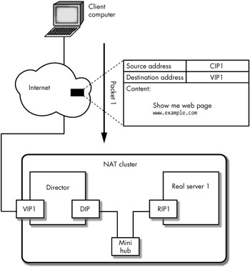
Figure 12-1: In packet 1 the client computer sends a request to the LVS-NAT cluster
As you can see in the figure, the client computer initiates the network conversation with the cluster by sending the first packet from a client IP (CIP1), through the Internet, to the VIP1 address on the Director. The source address of this packet is CIP1, and the destination address is VIP1 (which the client knew, thanks to a naming service like DNS). The packet's data payload is the HTTP request from the client computer requesting the contents of a web page (an HTTP GET request).
When the packet arrives at the Director, the LVS code in the Director uses one of the scheduling methods that were introduced in Chapter 11 to decide which real server should be assigned to this request. Because our cluster network has only one cluster node, the Director doesn't have much choice; it has to use real server 1, which has the address RIP1.
| Note | The Director does not examine or modify the data payload of the packet. |
In Chapter 14 we'll discuss what goes on inside the kernel as the packet passes through the Director, but for now we only need to know that the Director has made no significant change to the packet—the Director simply changed the destination address of the packet (and possibly the destination port number of the packet).
| Note | LVS-NAT is the only forwarding method that allows you to remap network port numbers as packets pass through the Director. |
This packet, with a new destination address and possibly a new port number, is sent from the Director to the real server, as shown in Figure 12-2, and now it's called packet 2. Notice that the source address in packet 2 is the client IP (CIP) address taken from packet 1, and the data payload (the HTTP request) remains unchanged. What has changed is the destination address— the Director changed the destination of the original packet to one of the real server RIP addresses inside the cluster (RIP1 in this example). Figure 12-2 shows the packet inside the LVS-NAT cluster on the network cable that connects the DIP to the cluster network.
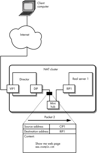
Figure 12-2: In packet 2 the Director forwards the client computer's request to a cluster node
When packet 2 arrives at real server 1, the HTTP server replies with the contents of the web page, as shown in Figure 12-3. Because the request was from CIP1, packet 3 (the return packet) will have a destination address of CIP1 and a source address of RIP1. In LVS-NAT, the default gateway for the real server is normally an IP address on the Director (the DIP), so the reply packet is routed through the director.[2]
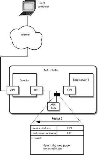
Figure 12-3: In packet 3 the cluster node sends a reply back through the Director
Packet 3 is sent through the cluster network to the Director, and its data payload is the web page that was requested by the client computer. When the Director receives packet 3, it passes the packet back through the kernel, and the LVS software rewrites the source address of the packet, changing it from RIP1 to VIP1. The data payload does not change as the packet passes through the Director—it still contains the HTTP reply from real server 1. The Director then forwards the packet (now called packet 4) back out to the Internet, as shown in Figure 12-4.
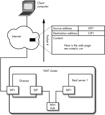
Figure 12-4: In packet 4 the Director forwards the reply packet to the client computer
Packet 4, shown in Figure 12-4, is the reply packet from the LVS-NAT cluster, and it contains a source address of VIP1 and a destination address of CIP1. The conversion of the source address from RIP1 to VIP1 is what gives LVS-NAT its name—it is the translation of the network address that lets the Director hide all of the cluster node's real IP addresses behind a single virtual IP address.
There are several things to notice about the process of this conversation:
-
The Director is acting as a router for the cluster network. [3]
-
The cluster nodes (real servers) use the DIP as their default gateway.[4]
-
The Director must receive all of the inbound packets destined for the cluster.
-
The Director must reply on behalf of the cluster nodes.
-
Because the Director is masquerading the network addresses of the cluster nodes, the only way to test that the VIP addresses are properly replying to client requests is to use a client computer outside the cluster.
| Note | The best method for testing an LVS cluster, regardless of the forwarding method you use, is to test the cluster's functionality from outside the cluster. |
Virtual IP Addresses on LVS-NAT Real Servers
If you need to offer client computers access to different services on separate VIP addresses, cluster nodes in an LVS-NAT cluster can also use multiple RIP addresses (IP aliases or secondary IP addresses) to identify the VIP address the client computer used in the original request. As you can see in Figure 12-5, the Director can be configured to send packets to the cluster nodes (real servers) using multiple virtual RIP addresses. In this scenario, client computers will still only know the VIPs configured on the Director; the Director is responsible for sending the packets into the cluster through the proper virtual RIP address (using a load-balancing or scheduling method).
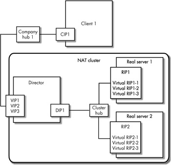
Figure 12-5: An LVS-NAT cluster with multiple VIPs
You might choose this scenario to load balance different types of users on different IP addresses. For example, accounting and reporting users might use one IP address, and customer service and simple transaction-based users would use another. You may also want to use IP-based virtual hosts for your web pages (see Appendix F for a detailed discussion of Apache virtual hosting).
Figure 12-5 shows the Director using three VIPs to receive network requests from client computers. The Director uses the LVS-NAT forwarding method to select one of the virtual RIP addresses on the real servers inside the cluster (any other LVS forwarding method could be used, too). In this configuration, the VIP addresses would normally be associated with the virtual RIP addresses, as shown in Figure 12-6.
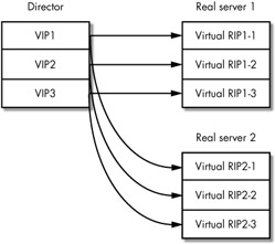
Figure 12-6: Multiple VIPs and their relationship with the multiple virtual RIPs
Like the VIPs on the Director, the virtual RIP addresses can be created on the real servers using IP aliasing or secondary IP addresses. (IP aliasing and secondary IP addresses were introduced in Chapter 6.) A packet received on the Director's VIP1 will be forwarded by the Director to either virtual RIP1-1 on real server 1 or virtual RIP2-1 on real server 2. The reply packet (from the real server) will be sent back through the Director and masqueraded so that the client computer will see the packet as coming from VIP1.
| Note | When building a cluster of web servers, you can use name-based virtual hosts instead of assigning multiple RIPs to each real server. For a description of name-based virtual hosts, see Appendix F. |
[1]For the moment, we will ignore the lower-level TCP connection establishment packets (called SYN and ACK packets).
[2]The packets must pass back through the Director in an LVS-NAT cluster.
[3]The Director can also act as a firewall for the cluster network, but this is outside the scope of this book. See the LVS HOWTO (http://www.linuxvirtualserver.org) for a discussion of the Antefacto patch.
[4]If the cluster nodes do not use the DIP as their default gateway, a routing table entry on the real server is required to send the client reply packets back out through the Director.
EAN: 2147483647
Pages: 219