Connectivity Types
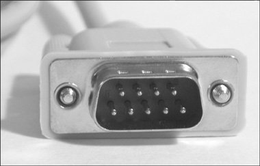
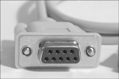
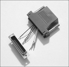
| To understand printing and troubleshoot it, you need to know details about the various methods of connectivity to printers. Without this information, any problems specific to a connectivity method are a mysterious black box. Local Serial PrintingSerial communication (through RS-232) is often used for terminals, modems, and other data communication devices. It is flexible and solid but relatively slow. Serial printing is one of the older printing methods, but it gives us a great chance to discuss in depth how local printing works. You can use RS-232 reliably with a cable up to about 15 meters (about 50 feet). This length depends on the quality of the cable, the amount of electromagnetic interference, and the baud rate (speed) at which you are communicating. The slower you communicate, the more reliable the data transmission. 9600 seems to be the best combination of reliability and speed for longer cables, but you can drop to 2400 or 1200 if needed. Serial ports can communicate to both DTE (data terminal equipment) and DCE (data circuit equipment) devices. DTEs are devices where data terminates such as a printer, terminal, PC, and so on. DCEs are devices that transmit data such as modems, CSUs, DSUs, and so on. This distinction is important because the primary problem with any serial communication is getting the right cable. Without the correct cabling, serial printing does not work. Cable quality is also an issue. Don't just pick up a cable out of a box in a storage room and assume it will work correctly. There are many types of cables, and each has a different pinout. The pins are the wires over which electrical signals travel. The pinout is the map that shows which pins on one end of the cable map to which pins on the other end. There are three main types of serial connection. They are DB-25 (25 pins), DB-9 (9 pins), and RJ-45 (8 pins, which is essentially a 4-pair network cable). A cable hood for DB-25 and DB-9 can either be male or female. Examples of male and female connectors are shown in Figures 11-4 and 11-5. Male hoods have the pins sticking out, and female hoods have holes to accept the male pins. Typically, cables have one male and one female end. Figure 11-4. A male DB-9 serial connector Figure 11-5. A female DB-9 serial connection There are usually at least three active pins in a serial cable. They are Rx (receive), Tx (transmit), and Gnd (ground). An example pinout is shown in Figure 11-6. In a DB-9 connector, DCE devices use pin 2 for Rx, pin 3 for Tx, and pin 5 for Gnd, and DTE devices use pin 3 for Rx, pin 2 for Tx, and pin 5 for Gnd. Figure 11-6. Simple DB-9 DCE to DB-9 DTE pinout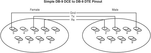 The serial device receiving the data uses flow control to let the sending device know that it has received all the data it can handle (for example, in a print buffer on a printer). This functionality is needed because a computer can send a print request faster than the printer can print it. The job is stored in buffer memory on the printer while it is printing. If the print job is bigger than the buffer, the printer needs to be able to tell the computer to stop sending more characters until it has freed space in the buffer. Serial printers usually use either hardware flow control (RTS/CTS) or software-based flow control (XON/XOFF). There are pins on a serial connection that can be used for hardware data flow control when printing such as RTS (request to send) or CTS (clear to send). When the receiving device is ready to accept data, it raises (sends an electric signal on) its RTS pin. This signal comes across to the other end of the cable on the CTS pin and indicates that it is ok to transmit data. If the print buffer in the printer fills up, the printer drops the CTS signal, and the computer holds additional data until the CTS is raised again. Figure 11-7 shows how the pins connect to the wires when the housing is opened. Figure 11-7. A serial connector dismantled We will not discuss the other pins not commonly used in printing such as CD (carrier detect), DSR (dataset ready), DTR (data terminal ready), and others. To communicate with a local serial printer, you use a device file. An example of a serial device file is the following: crw-rw---- 1 root uucp 4, 64 Jan 2 07:31 ttyS0 You can get information about a serial port by using the setserial command: # setserial /dev/ttyS0 /dev/ttyS0, UART: 16550A, Port: 0x03f8, IRQ: 4 You can gather additional settings data about a serial port by using the sty command. The stty command enables you to print and manipulate serial line settings such as speed, the bit setting, parity, character translation, number of columns, and so on. Here is an example output from stty that reports all the current settings on a serial port: # stty -F /dev/ttyS0 -a speed 9600 baud; rows 0; columns 0; line = 0; intr = ^C; quit = ^\; erase = ^?; kill = ^U; eof = ^D; eol = <undef>; eol2 = <undef>; start = ^Q; stop = ^S; susp = ^Z; rprnt = ^R; werase = ^W; lnext = ^V; flush = ^O; min = 1; time = 0; -parenb -parodd cs8 hupcl -cstopb cread clocal -crtscts -ignbrk -brkint -ignpar -parmrk -inpck -istrip -inlcr -igncr icrnl ixon \ -ixoff -iuclc -ixany -imaxbel opost -olcuc -ocrnl onlcr -onocr -onlret -ofill -ofdel nl0 cr0 tab0 bs0 \ vt0 ff0 isig icanon iexten echo echoe echok -echonl -noflsh -xcase -tostop -echoprt echoctl echoke If the printer is connected and set up correctly, you should be able to send a file using cat to the device, and it should come out on the printer. It may look funny because of formatting or line feed issues. # cat afile > /dev/ttyS0 This command opens the serial port and transmits the data across the transmit pin to the printer. The printer then takes the data and prints it. However, the data might be stair-stepped, which looks like this: See Dick run.
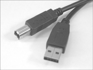
This error happens because of a mismatch in end of line characters. In Linux and UNIX, the end of line is signaled in text streams by a line feed (LF). You will sometimes also see this notated with a \n character. With DOS, Windows, and other systems, an end of line comprises a carriage return and a line feed (CR/LF). If you look at the stty options, you can see that the onlcr option specifies whether an LF should be changed into CR/LF. To set the onlcr flag, run this command: # stty -F /dev/ttyS0 onlcr To unset the onlcr flag, use: # stty -F /dev/ttyS0 -onlcr To set a baud rate for a serial line to 9600 baud, issue the following command: # stty -F /dev/ttyS0 9600 Flow control is primarily an issue with slower printers and longer cables. Flow control problems can cause characters or strings of characters to be dropped in job. The characters can be dropped from the middle or end of the job. This problem can be addressed in three ways. The first solution is to slow the baud rate over the serial line. This solution is imperfect, but it works well in a lot of cases. Second, you can switch the printer from software flow control to hardware flow control. The signaling on hardware flow control is more precise, so timing issues and missed signals are less likely. Last, you can adjust the closing_wait setting on the serial port with the set_serial command. This option is volatile, meaning that it only lasts until the next reboot. The way around this issue is to place the set_serial command in an rc script such as /etc/rc.serial. This method changes the amount of time after close before the serial port buffer is flushed. The default time is 30 seconds. If you don't have a copy of rc.serial, look for a template under /usr/share/doc/setserial*/rc.serial. These and other settings can usually be controlled from the spooler's configuration files or rc files. We discuss this subject in further detail in the sections on each spooler type. Local USB PrintingUSB has quickly become the default for attaching peripherals to a computer. It is easy to use and fast. It has supplanted parallel (ISEE 1284) as the default method for printing. Most inkjet printers come with at least one USB port. Some have both USB and parallel ports. There are two current standards for USB devices. USB 1.1 runs at 12Mbps, and USB 2.0 runs at 480Mbps. Both standards accept up to 127 peripherals per bus. USB also supports Plug-and-Play installation and hot plugging. The maximum length for a USB cable according to the standard is 16 feet. USB devices can either draw power from the USB bus or be externally powered. This choice depends on the power needs of the device. There are two types of connectors on a USB cable. They are referred to as type A and type B connectors. The connectors can either be mini- or standard-sized. The type A connector is male and plugs into the female port on the computer. The type B connector is male and connects into the peripheral. You can see examples of connectors in Figure 11-8. Figure 11-8. Standard-sized type A and type B USB connectors To effectively use USB printing, you should have at least a 2.4 kernel. To use USB 2.0, you should have a late 2.4 or 2.6 kernel. The USB printers use device files similar to /dev/usb/lp0. The last digit increments with each printer added. Non-CUPS spoolers can be confused by the printer device files because USB device files are assigned and removed dynamically. If they are powered on or detected in different orders, the device files could reverse, which could cause print requests to go to the wrong printer. CUPS uses a USB abstraction layer and the printer's manufacturer, model, and printer serial number to send the print job to the correct printer. To gather more information about what USB devices are attached to a system, you can run the following command: # lspci v 00:10.0 USB Controller: VIA Technologies, Inc. VT82xxxxx \ UHCI USB 1.1 Controller (rev 80) (prog-if 00 [UHCI]) Subsystem: Micro-Star International Co., Ltd.: Unknown device 3902 Flags: bus master, medium devsel, latency 32, IRQ 11 I/O ports at d800 [size=32] Capabilities: [80] Power Management version 2 00:10.1 USB Controller: VIA Technologies, Inc. VT82xxxxx \ UHCI USB 1.1 Controller (rev 80) (prog-if 00 [UHCI]) Subsystem: Micro-Star International Co., Ltd.: Unknown device 3902 Flags: bus master, medium devsel, latency 32, IRQ 3 I/O ports at dc00 [size=32] Capabilities: [80] Power Management version 2 00:10.2 USB Controller: VIA Technologies, Inc. VT82xxxxx \ UHCI USB 1.1 Controller (rev 80) (prog-if 00 [UHCI]) Subsystem: Micro-Star International Co., Ltd.: Unknown device 3902 Flags: bus master, medium devsel, latency 32, IRQ 10 I/O ports at e000 [size=32] Capabilities: [80] Power Management version 2 00:10.3 USB Controller: VIA Technologies, Inc. USB 2.0 (rev 82) (prog-if \ 20 [EHC I]) Subsystem: Micro-Star International Co., Ltd.: Unknown device 3902 Flags: bus master, medium devsel, latency 32, IRQ 5 Memory at ea001000 (32-bit, non-prefetchable) [size=256] Capabilities: [80] Power Management version 2 And then: # cat /proc/bus/usb/devices T: Bus=04 Lev=00 Prnt=00 Port=00 Cnt=00 Dev#= 1 Spd=12 MxCh= 2 B: Alloc= 0/900 us ( 0%), #Int= 0, #Iso= 0 D: Ver= 1.10 Cls=09(hub ) Sub=00 Prot=00 MxPS= 8 #Cfgs= 1 P: Vendor=0000 ProdID=0000 Rev= 2.06 S: Manufacturer=Linux 2.6.9-1.681_FC3 uhci_hcd S: Product=UHCI Host Controller S: SerialNumber=0000:00:10.2 C:* #Ifs= 1 Cfg#= 1 Atr=c0 MxPwr= 0mA I: If#= 0 Alt= 0 #EPs= 1 Cls=09(hub ) Sub=00 Prot=00 Driver=hub E: Ad=81(I) Atr=03(Int.) MxPS= 2 Ivl=255ms T: Bus=03 Lev=00 Prnt=00 Port=00 Cnt=00 Dev#= 1 Spd=12 MxCh= 2 B: Alloc= 0/900 us ( 0%), #Int= 0, #Iso= 0 D: Ver= 1.10 Cls=09(hub ) Sub=00 Prot=00 MxPS= 8 #Cfgs= 1 P: Vendor=0000 ProdID=0000 Rev= 2.06 S: Manufacturer=Linux 2.6.9-1.681_FC3 uhci_hcd S: Product=UHCI Host Controller S: SerialNumber=0000:00:10.1 C:* #Ifs= 1 Cfg#= 1 Atr=c0 MxPwr= 0mA I: If#= 0 Alt= 0 #EPs= 1 Cls=09(hub ) Sub=00 Prot=00 Driver=hub E: Ad=81(I) Atr=03(Int.) MxPS= 2 Ivl=255ms T: Bus=02 Lev=00 Prnt=00 Port=00 Cnt=00 Dev#= 1 Spd=12 MxCh= 2 B: Alloc= 0/900 us ( 0%), #Int= 0, #Iso= 0 D: Ver= 1.10 Cls=09(hub ) Sub=00 Prot=00 MxPS= 8 #Cfgs= 1 P: Vendor=0000 ProdID=0000 Rev= 2.06 S: Manufacturer=Linux 2.6.9-1.681_FC3 uhci_hcd S: Product=UHCI Host Controller S: SerialNumber=0000:00:10.0 C:* #Ifs= 1 Cfg#= 1 Atr=c0 MxPwr= 0mA I: If#= 0 Alt= 0 #EPs= 1 Cls=09(hub ) Sub=00 Prot=00 Driver=hub E: Ad=81(I) Atr=03(Int.) MxPS= 2 Ivl=255ms T: Bus=01 Lev=00 Prnt=00 Port=00 Cnt=00 Dev#= 1 Spd=480 MxCh= 6 B: Alloc= 0/800 us ( 0%), #Int= 0, #Iso= 0 D: Ver= 2.00 Cls=09(hub ) Sub=00 Prot=01 MxPS= 8 #Cfgs= 1 P: Vendor=0000 ProdID=0000 Rev= 2.06 S: Manufacturer=Linux 2.6.9-1.681_FC3 ehci_hcd S: Product=EHCI Host Controller S: SerialNumber=0000:00:10.3 C:* #Ifs= 1 Cfg#= 1 Atr=e0 MxPwr= 0mA I: If#= 0 Alt= 0 #EPs= 1 Cls=09(hub ) Sub=00 Prot=00 Driver=hub E: Ad=81(I) Atr=03(Int.) MxPS= 2 Ivl=256ms You can see that devices that have Spd=12 are USB 1.x and Spd=480 are USB 2.0. Local Parallel PrintingThe IEEE 1284 standard is bidirectional, but Linux drivers are write-only. This means you receive no status or error information from the printer. Centronics is the de facto standard for parallel cabling. It has a 36-pin hood to connect to the printer and a 25-pin connector to plug into the computer's parallel port. When the new kernel is booted, the printer should be identified automatically. To check, you can run: cat /proc/sys/dev/parport/parport0/autoprobe # dmesg |grep i lp The device file is of the format /dev/lp0. The last number of the device file increments for each device on a parallel port. Parallel ports can be configured as Standard Parallel Port (SPP), Bidirectional Parallel Port (BPP), Enhanced Parallel Port (EPP), or Enhanced Capabilities Port (ECP). EPP and ECP are the most common on modern computers. They are extensions on Centronics and SPP. EPP and ECP are much faster than the original Centronic/SPP standard and have improved handshaking and flow control. The mode is generally set in the computers BIOS. The best setting is a combination of EPP/ECP (if it is offered). If EPP/ECC is not available, you can try to fall back to ECP. Several versions of EPP are available. If possible, you should select EPP 1.9. This selection sometimes requires experimentation, though. If you are still having problems, you might also try SPP and see how that works for you. Because the Linux driver is not bidirectional, you only lose the speed and handshaking advantages of the other modes. As with RS-232, parallel printing is extremely sensitive to cabling issues. Make sure the cable is a good-quality IEEE 1294 cable. Also try to minimize the cable length. It is possible to make parallel printing work up to 50 meters, but it becomes problematic past 15 meters. Remote PrintingRemote printing over port 515 is based on the computing standard RFC1179 created by the Internet Engineering Task Force (IETF). RFC stands for Request For Comment. This method is how a proposed standard is documented and published to the Internet community for feedback. These standards form the communication protocols that make up the Internet (such as HTTP). RFC1179 and other RFCs are available from http://www.ietf.org/rfc. The technology specified by RFC1179 can be used for printing to another system's spooler. This functionality enables you to print remotely to printers that are locally attached to another system. The other system could be a terminal server, a print server, or a computer. It is important to understand what format is used for RFC1179 printing. The RFC states the following:
One disadvantage to RFC1179-style printing is that many of the command-line options are not passed between the two systems. The options passed are very limited. For example, the landscape option would not be passed. The spooler sends two files for each remote print request. The first is a control file, and the second is a data file. The files can be sent in any order to the remote spooler. The control file contains information about the print request (such as user ID, queue name, and so on). The control filename is in the format cfAzzzhostname, where the zzz is a three-digit job number and hostname is the hostname of the sending system. These files are stored in the spooler's temporary directories. The print request transfer begins by sending a control string to the remote spooler. This is generally one of three strings. The first is an abort string. The second lets the spooler know that a control file is being transferred, and the last lets the spooler know that a data file is being sent. The control file contains multiple lines of data. Each line is a separate parameter. The first character of each line is a command character followed by the variable data. RFC1179 also provides for requesting the status of a print queue, limited control over changing queue status, and canceling a print request. Control FilesA typical control file contains the following data: Hhost.domain.tld J/home/usera/afile /home/usera/bfile CA Lusera Pusera fdfA003host.domain.tld N/home/usera/afile UdfA003host.domain.tld fdfB003host.domain.tld N/home/usera/bfile UdfB003host.domain.tld This is not gibberish. All it takes is the secret decoder ring. It is a series of commands to the remote spooler. Each line is executed one after another. In this example, usera on system host.domain.tld has printed two files (/home/usera/afile and /home/usera/bfile).
The f, N, and U commands are repeated again for the second file. There are many other possible control characters in a control file. They are all defined in RFC1179. Also be aware that some spoolers also add their own proprietary extensions to the control file. These are used when printing between two spoolers of the same type. Data FilesThe data file contains the file or text stream that was submitted to be printed. Data is usually submitted by specifying a file to be printed or by redirecting STDIN to the print command. The data filename is in the format dfAzzzhostname, where the zzz is a three-digit job number and hostname is the hostname of the sending system. There can be more than one data file if more than one were submitted to be printed in one job. After the control and data files are transferred, the remote spooler should return a status code. For example, \000 indicates success. Anything else indicates an error. ContentionHow does remote printing handle contention? The jobs are accepted and spooled to the remote print queue. There, the jobs wait in the queue until it is their turn to print on the printer. Troubleshooting ToolsRemote printing troubleshooting tools include the following:
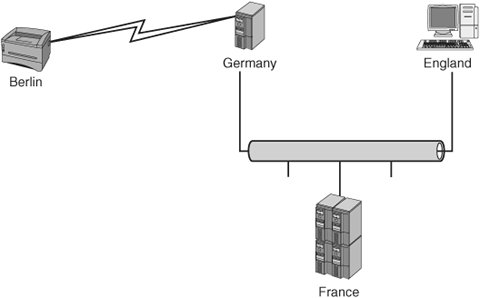
Scenario 11-1: Unable to Print to Remote PrinterA user received the following error: $ lpr /home/user/Billy.txt $ lpq could not talk to print service at germany To troubleshoot this situation, you would do something like the following:
Other possible causes of this type of error include the following:
Raw Network Socket PrintingThis type of printing was pioneered by Hewlett-Packard, but most printers with network connections support raw network printing. The main port for these transfers is port 9100, but on multiport print servers, it is also possible to send print jobs to ports 9101 and 9102. This is called raw printing because the port is opened and the raw text stream is then transferred to the device. There is no queue or spooler on the other end to receive the print request. Any formatting or other control characters must be embedded into the raw text stream. The network device can also send back status or error messages while the connection is open. The connection is kept open until the request finishes transferring. Note Microsoft calls this Standard TCP/IP port printing. These print servers can be cards inside the printer that allow connection to the network or external boxes with ports to connect the printer to a network connection. Just to confuse things further, many networked printers support printing to both ports 515 and 9100. For example, Hewlett-Packard JetDirect print servers also accept RFC1179 print requests to the queues raw and text. One important question is: "How does the print device obtain its IP address and netmask?" Most network printers can obtain their configuration in several ways. The configuration can be hard coded through the front panel or a network interface (TELNET or HTTP), or dynamically through DHCP and bootp. Bootp and DHCP (which is newer and more capable) both are used to dynamically assign networking information to network devices. The vast majority of printing through port 9100 is done to print servers, but it is possible to set up a UNIX or Linux system to accept print requests this way. This is done by adding a new service line to /etc/inetd.conf. Two examples of this are
ContentionHow does a print server such as HP's JetDirect handle device contention? They are relatively simple devices and have no spooler. They just have a print buffer. When the print device is busy printing, all the other hosts must retry until the print server is free. Troubleshooting ToolsTroubleshooting tools for working on raw network socket printing problems include the following:
IPP
IPP is a new client/server print protocol that was designed in cooperation with the IETF. IPP is designed with networks and shared resources in mind. All printer and job objects are defined using a Uniform Resource Locator (URL), just like what is used for other Internet-based services such as HTTP, FTP, and so on. Unlike other protocols, IPP also supports access controls, Basic, Digest, and Certificate authentication, LDAP integration, and SSL and TLS encryption. Many new network printers and print servers include built-in IPP capabilities. The IPP standard is defined in the following documents from the IETF:
Five key terms are needed to understand IPP. They are IPP printer, IPP client, privileged operator, job, and notification service. IPP can use port 631 or port 80. Port 631 is the most commonly used. Here is an example of a URL for an IPP print device: # lpstat v Laser device for Laser: ipp://localhost/ipp IPP uses standard HTTP POST and GET commands to enable bidirectional communication with print devices. It uses a special "application/ipp" MIME Content-Type. IPP allows normal push printing, but it also has the capability to perform pull printing, in which a server or printer is told the URL of a document, which is then pulled from that URL and printed. The IPP RFC breaks down the capabilities of IPP printing into six categories:
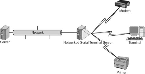
Next is an example of a POST-based communication with an IPP device. POST /ipp/ HTTP/1.1 Content-Length: 285 Content-Type: application/ipp Host: 192.168.2.33 Terminal Servers (Networked Serial)A terminal server (see Figure 11-10) is a piece of networked hardware that provides multiple users with access to terminal and console ports, modems, printers, and other serial devices. A terminal server can be either a piece of custom hardware or a standard computer system with a large number of serial ports. In either case, a terminal server provides a way to enable hardware to be accessed from multiple systems, and it provides network access to devices that don't ordinarily have it. There are two main ways to access devices connected to terminal servers. The first is a direct network connection through specific ports. The other is to use drivers on the client to packetize communication to local device files and forward it to the terminal server. Configuration varies between terminal server manufacturers. Figure 11-10. A terminal server |
EAN: 2147483647
Pages: 129