3.3 Routing design issues
|
|
3.3 Routing design issues
3.3.1 Routing tables
A dynamic routing protocol typically creates a number of topology-related databases in memory, holding key information on neighbors, locally configured interfaces, statically configured information, and routing information acquired from peers. All of this information is used to construct a routing table—a list of routing entries that is consulted whenever a router makes a packet forwarding decision (actually, for performance reasons, there is often a separate forwarding table, derived from the routing table, which holds the shortlist of the active preferred routes, held in data structures that enable rapid traversal and retrieval).
3.3.2 Routing entry types
There are several types of routing table entries, including the following:
-
Static routing entries are fixed table entries, usually configured by a network operator for special purposes, such as default routes, preferred routes, or host routes. Static routing is also commonly used for permanent paths such as point-to-point WAN links to remote sites or dial-up ISDN lines, where there is no alternate path and, therefore, no need for the overhead of a dynamic routing protocol. In recent years several router vendors have associated preference values with static routing entries.
-
Dynamic routing entries are automatically generated by dynamic routing protocols, such as OSPF and EIGRP. The routing table is populated through a learning process, using direct knowledge of the local topology and information acquired from neighboring routers. Dynamic routing reflects the true state of the network by automatically responding to topology changes and reflecting those changes in the routing table.
-
Direct interface routing entries are routes where the destination network or subnetwork is on a directly attached physical interface (i.e., there is no next hop).
-
Default routes are a special form of static route. A default route identifies a default router to which all traffic should be forwarded if the destination address is unknown (i.e., not included in the routing database). While default routing has its advantages, it can lead to loss of control over certain types of traffic. For example, hosts may occasionally send packets to nonexisting hosts (so-called Martian Hosts). If a default route is configured, then, instead of being dropped, these packets will be forwarded over the default route.
3.3.3 Routing metrics
In order to determine best paths in a network topology, there must be some cost component that can be used to compare alternate choices. The fundamental cost element used in networks is the interface metric. There are three broad metric implementations, largely dependent upon the type of routing entry and the class of routing protocol used. These implementations are as follows:
-
Hop count—A link metric may be a simple hop count—a metric most commonly associated with distance-vector protocols. Some distance-vector protocols allow hop counts to be configured, which enables differences in line speed, asymmetry, or geographic preferences to be imposed.
-
Abstract value—Some interface metrics are integer values that may be customized. Often, these metrics automatically default to values calculated from interface line speeds but can be overridden, using arbitrary values, by the network designer. For example, OSPF offers a two-byte integer. This metric could be tuned to almost any scheme the designer creates. IS-IS offers a similar scheme.
-
Combinatorial—Some routing protocols offer more sophisticated metrics based on a combination of metrics, such as available circuit bandwidth, monetary cost, reliability, congestion, latency, delay, jitter, Round-Trip Time (RTT), and so on. These protocols would need to include more sophisticated (possibly proprietary) feedback mechanisms on aspects of network utilization and to ensure that topology oscillation does not occur when performance changes rapidly.
3.3.4 Path selection
In a very simple network topology, there may be only one physical and logical path between a source and a destination. This makes route selection trivial and negates the need for any dynamic routing protocol (i.e., routes could be configured statically). In more complex topologies, dynamic routing protocols must figure out the best path at a particular time between a particular source and destination from a wide range of possibilities. Should the topology fail at any point, then the routing protocol must also respond to those changes by establishing new paths, if available. (See Figure 3.3.)
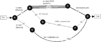
Figure 3.3: Based on various path selection criteria and the routing algorithm chosen, any number of bad choices could be made in selecting the optimum path.
Single path or multipath
The advantages of multipath algorithms are clear; they can provide substantially greater throughput and also offer topological robustness. Multipath algorithms typically allow traffic to be multiplexed over several circuits (WAN or LAN) according to a range of criteria, as follows:
-
Packet based—Traffic may be load balanced on a per-packet basis using round-robin techniques. Usually one packet or destination is distributed to each possible path in turn.
-
Session based—Traffic may be load shared on a session or flow basis, typically by using source-destination or destination hash function. This technique tends to preserve packet order.
The distribution algorithm may mandate equal end-to-end aggregate metrics (as with OSPF) or may perform fair load distribution over different speed links with different end-to-end aggregate metrics (as with EIGRP). Some topologies may also mandate that send and return paths are consistent (e.g., stateful firewall configurations).
Note that this form of load sharing should not be confused with lower-level, point-to-point load-sharing techniques, such as offered by Multi-Link PPP (MLPPP [1]). Such techniques are transparent to routing protocols and will reorder packets into a single stream before delivery to the routing layer. In Figure 3.3, for example, link B-C comprises four ISDN circuits aggregated via MLPPP. From the routing protocol perspective this simply appears as a single 256-K circuit.
Choosing the best paths
The problem for a router is how to decide what the best path is, especially when there are contradictory issues to consider [1]. A number of factors should be taken into account in order to determine the optimum path, including the following:
-
Routing metrics (aggregate hops, abstract metric, combinatorial, etc.)
-
Throughput, delay, congestion
-
Link stability
-
Real-world cost
As a general rule, routing protocols simply compare aggregate link metrics to select the best path from a group of possible paths. With increasing interest in service quality, performance optimization, and cost reduction, an approach more intelligent than automatic metrics is required, which considers more of the factors that make links attractive.
A routing protocol doesn't have quite a clear view. For example, the distance-vector protocol RIP would see no problem in selecting A-E-D; after all, it's only two hops from router A (in fact the optimum path here has the highest aggregate number of hops). OSPF does better, giving us the option of either A-G-F-D, A-B-C-D, or both (using equal cost multipath load sharing). With EIGRP we have even more options, and we would not necessarily have to modify any metrics. EIGRP can load balance over multiple hops of unequal cost, weighting traffic proportionally if necessary.
The point here is that the design choices are far from simple, and, by insulating the routing protocol from the real nature of the network, we blur its view of network to the point where the network designer must take an active part in the choices made. This has led to initiatives such as Multi-Protocol Label Switching (MPLS), which provides sufficient granularity to switch individual flows, each with its own service characteristics.
3.3.5 The IP forwarding decision
When an IP packet arrives at the interface of a router, a decision must be made whether to forward that packet and, if so, onto which interface(s). These decisions are made by the IP forwarding algorithm and lookups to tables such as the local Forwarding Table and ARP cache held on the device. Figure 3.4 illustrates the basic routing algorithm used by an IP device.
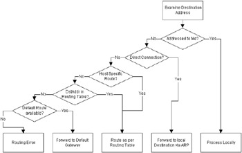
Figure 3.4: Conceptual flowchart illustrating the IP forwarding algorithm.
Forwarding algorithm
When an IP packet arrives at an interface on a router, the router will first decide if the packet is destined for itself (perhaps an SNMP poll or part of a telnet session into the management console) or for a remote network or subnetwork. To determine whether destinations are local or remote, the packet's destination IP address and associated mask are ANDed and compared with each of the receivers' local interfaces (each with their own IP addresses and ANDed network mask).
If the address-mask comparison fails, then the packet is determined to be for a remote network, in which case the router performs a longest prefix matched lookup in the forwarding table, and the packet is sent to the next-hop router. Routing tables are typically created by the use of dynamic routing protocols and/or users populating the tables with static routes.
If the address-mask comparison is successful for a particular interface, then the packet is forwarded directly to that interface.
In either case, ARP is required to resolve the Layer 2 address of the next-hop router. The appropriate Layer 2 address will be used to replace the MAC destination address before the frame is transmitted (i.e., the next-hop router MAC address or host address). The ARP cache is maintained dynamically by the router (or host), although, again, it may contain static entries configured by the user. Aside from static ARPs, each entry in the ARP cache will have a timer associated with it to flush out an entry and ensure that the cache is a true reflection of the network.
The prefix-based route lookup operation is particularly time consuming, especially with large table sizes. This is a concern for backbone routers, where forwarding tables are typically in excess of 50,000 route entries. We briefly review the concepts of route lookup next.
Route lookup
As described earlier, IP is datagram based, and whenever a packet is scheduled for forwarding, a router tries to match the packet's destination address in its forwarding table to determine the destination port (or interface). The forwarding table stores routing entries of the form:
-
<network address><mask><port>
The destination address is parsed from the received packet, and the router iterates through all of its forwarding table entries for matches. For each entry, the router masks the destination address with the mask associated with that entry. If a match is found, the port associated with the entry is appended to a set of candidate destination ports. The destination port ultimately chosen will be the candidate with the largest mask (referred to as the longest prefix match), since this is the most specific choice available (note that this assumes that contiguous masks are mandated, since noncontiguous masks would mean that there may be no better algorithm for route lookup than an iterative search of all entries). For example, a packet with destination address 146.30.225.5 arrives at a router. The router has the following entries in its forwarding table:
| Entry | Distance Address | Prefix | Distance Port |
|---|---|---|---|
| 1 | 130.42.3.0 | /24 | 1 |
| 2 | 146.30.1.5 | /16 | 6 |
| 3 | 146.30.225.0 | /18 | 2 |
| 4 | 193.168.32.0 | /24 | 11 |
| 5 | 146.0.0.0 | /8 | 3 |
| 6 | 2.2.5.0 | /8 | 16 |
| 7 | 146.30.230.0 | /19 | 14 |
After a route lookup there are four address matches found in the forwarding table (entries 2, 3, 5, 7), and so the set of candidate destination ports for this packet is (2, 3, 6, 14). Since entry 7 has the longest prefix (19 bits), the destination port selected is port 14.
3.3.6 Convergence
When a topology change is detected in a routing network, it must be propagated to other routers and a new topology must be calculated. During this period it is possible for the behavior of the network to become unpredictable; packets could be sent in routing loops or can disappear completely into black holes. The time taken for a community of routers to detect changes and reconfigure the topology correctly is called convergence time. Clearly, it is imperative that this value be kept low. Convergence time is influenced by several factors, some of which can be influenced directly by the designer, as follows:
-
The speed with which local hardware failures are detected and flagged to higher-layer routing software
-
Tunable parameters, such as hello timers, dead intervals, hold-down timers, cache-aging timers, and so on
-
The size of the network (number of routers, link speeds, routing delays)
-
Network topology
-
Choice of routing protocol (link-state, distance-vector, hybrid)
In general, link-state routing protocols converge much faster than distance-vector protocols (in the order of several seconds as opposed to minutes). The notable exception is Cisco's EIGRP, which converges at rates comparable to OSPF and IS-IS.
3.3.7 End-system routing
Devices such as servers and workstations must be able to locate routers when they need to access devices external to the local network. The main problem here is how to get the end system to learn the whereabouts of its nearest router without imposing a full routing stack on the device. A subsidiary problem is how to make those configuration data manageable on large networks with potentially thousands of hosts. The fancy name for this functionality is End System to Intermediate System routing (or ES-IS—in fact, OSI provides a protocol called ES-IS to do this very thing). There is currently no uniformly agreed-upon method for end stations to locate routers in the IETF/IP world. In essence there are two main possibilities: static gateway configuration and dynamic router discovery. Note that the term gateway is used here just to add an extra layer of confusion. In many early IETF standards the term "gateway" is synonymous with router. This terminology still persists in the client configuration.
Static gateway configuration
Gateway configuration involves the nomination of a primary (and possibly secondary) gateway. The simplest way to tell a station where its nearest router is to configure it explicitly by manually editing a file with the address and mask. For example, under Windows 98 you would simply edit network properties for the TCP/IP protocol service (see Figure 3.5). This means that no protocol is required, and whenever the station needs to send a packet to a remote destination it simply forwards that packet to the nominated router. The station can easily work out whether the packet is local or remote by comparing the destination address and mask with its own address and mask. If the station does not know the MAC address of the router then ARP is used as standard.
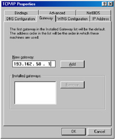
Figure 3.5: Default gateway configuration under Windows 98.
One drawback of this scheme is fault tolerance. If the primary gateway dies, then there is no way for the station to send packets remotely. To counter this, many implementations support the concept of a secondary gateway. The secondary gateway will be used in the event that the primary gateway cannot be reached (say the ARP cache entry times out, and all subsequent ARP requests are never responded to). Another drawback is maintenance. While this scheme is fine for small networks, where change can be managed easily, on large, dynamic internetworks this is simply not scalable. To deal with large system configuration, many network designers enlist the use of DHCP DHCP servers dynamically allocate default gateways from a pool; usually there is a default gateway assignable on a per-subnet basis.
Dynamic router discovery
When multiple routers are attached to a host's local segment, the host should ideally locate the router that offers the optimal path to a particular destination and should be aware of topology changes. This process of dynamically finding routers is called router discovery. The following are router discovery protocols:
-
RIP
-
OSPF
-
End System to Intermediate System (ES-IS)
-
Proxy Address Resolution Protocol (ARP)
-
ICMP Router Discovery Protocol (IDRP)
3.3.8 Choosing a routing strategy
Choosing an interior gateway protocol
Choosing the IGP most appropriate for your network is almost never a purely technical decision. There are often commercial and even company-political issues to consider, especially in large organizations. Table 3.2 lists several of the key characteristics of IGPs. The following items are just some of the considerations you must make when choosing a routing protocol:
-
Protocols to transport
-
Network size and scalability
-
Standards and interoperability
-
Ease of deployment and maintenance
-
Network management and debugging facilities
-
Convergence time
-
Router vendor
| Routing Protocol | Subnet Support | Multi Protocol | Metric | Load Sharing | Open Standard | Convergence | Routing Algorithm | Complexity |
|---|---|---|---|---|---|---|---|---|
| RIPv1 | No | No | Hop | No | Yes | Slow | dv | Low |
| RIPv2 | Yes | No | Hop | No | Yes | Slow | dv | Low |
| Cisco IGRP | No | No | Combined | Yes | No | Slow | dv | Low |
| Cisco EIGRP | Yes | Yes | Combined | Yes | No | Fast | dv+ | Moderate |
| OSPF | Yes | No | Abstract | Yes | Yes | Fast | spf | High |
| IS-IS | Yes | Yes | Abstract | Yes | Yes | Fast | spf | High |
| Note that although dual IS-IS is multiprotocol it supports only OSI and IP packets. EIGRP based on distance-vector techniques. | ||||||||
If your network is IP only, you have a range of protocols to choose from, including RIP, OSPF, IGRP, EIGRP, and IS-IS. If your network is multiprotocol, then you may need to run IGRP or EIGRP. For a pure OSI network you would most probably choose IS-IS.
In small networks, where there is very little skill on site and the application requirements are not stringent, RIP is a reasonable choice. It is very easy to set up and quite robust. Neither IS-IS nor OSPF is intuitive for novice engineers; both involve a degree of complexity and require at least some understanding of their theory and operational characteristics. EIGRP is meant to fuse the simplicity of distance-vector protocols such as RIP with the performance benefits of link-state protocols such as OSPF. Figure 3.6 provides a simple decision system for assessing which IGP is appropriate for your network.
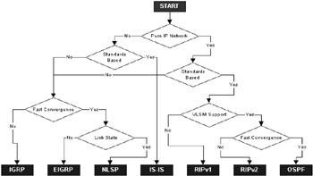
Figure 3.6: Simple flowchart for possible IGP selection.
RIP is suitable for a small network (say, up to a dozen routers) and is also commonly used as an ES-IS protocol to provide hosts with limited routing awareness (i.e., instead of a static default gateway configuration, described earlier in this chapter). If you require load balancing, then RIP cannot be used. If your network uses Variable-Length Subnet Masks (VLSM), then RIP and IGRP cannot be used since they do not carry mask data and must, therefore, assume either natural masks or use mask information associated with local interfaces. RIPv2 does support VLSM. For medium to large networks you would be strongly advised not to use a pure distance-vector protocol. These protocols scale very badly and are very inefficient in their use of bandwidth. Distance-vector protocols converge very slowly in comparison to link-state protocols such as OSPF and IS-IS. RIPv2 does scale a little better than RIPv1, but it is generally regarded as too little too late. RIP was never really intended for anything other than modest local network topologies.
OSPF, EIGRP, and, increasingly, IS-IS are the main contenders for large network design (each converges quickly, on the order of several seconds). OSPF is essentially state of the art, and is the prime interior protocol for large IP routed environments; OSPF is very widely deployed in a range of environments (corporate enterprise, regional backbone networks, health care, finance, and so on). IS-IS (particularly integrated IS-IS, which can route both OSI and IP protocols simultaneously) is also technically a very strong candidate for medium to large IP networks; however, it is not widely deployed at present (restricted mainly to backbone telco networks and government applications). With IS-IS you are likely to have to redistribute routes in and out of the IS-IS domain, and you may not wish to add another layer of complexity.
If you have a pure Cisco site, then you may have been persuaded to deploy EIGRP (although Cisco is nowadays equally happy to promote the benefits of OSPF). EIGRP is a hybrid distance-vector protocol that scales well. Although proprietary, since Cisco has by far the largest installed base of routers, including the Internet, one could argue that EIGRP is a de facto standard. EIGRP is a mature protocol and has the advantage of rich, multiprotocol features—a strong advantage in multiprotocol enterprise networks. However, now that IP has become so pervasive the potential advantages of EIGRP over OSPF are becoming less clear. In multivendor environments EIGRP would have to be redistributed (e.g., into OSPF) to allow interoperability, and this is an extra layer of complexity you may want to avoid.
If you are running a large BAY (now part of Northern Telecom) network, you will almost certainly be running OSPF, since BAY was one of the chief proponents of OSPF when it was first made available (alongside pioneering companies such as Proteon). My personal preference for medium to large internetworks is OSPF, mainly because of its ability to converge very quickly and scale across a range of environments and also because it is an open standard and interoperates well in multivendor environments.
|
|