Graphics
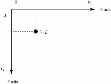
| One of the most enticing aspects of a computer is its capability to render graphical content. Right now, you're probably eager to use the AWT to create some graphics. However, before you can let your imagination and creativity run rampant, you first need to learn about the AWT's approach to drawing. The Fundamentals of DrawingIn the last chapter, you learned that JFC applets (or just applets for short) are assigned rectangular display areas in which to draw their output. These display areas (also known as drawing surfaces ) are implemented as objects created from subclasses of the AWT's abstract Component class. Although Component will not be discussed until the next chapter, its influence is pervasive throughout the AWT. Keep this influence in mind as you read this chapter. Note Applications can also use drawing surfaces. However, because applications do not default to using these surfaces, you must explicitly create an application with a drawing surface in mind. Such applications are known as JFC applications. You will learn how to create JFC applications in later chapters. Each drawing surface consists of small colored dots called picture elements ( pixels ) or points. The exact number of pixels on a drawing surface is controlled by that surface's width and height. Tip The Component class provides a getSize method that returns an object created from the Dimension class. This class contains two public field variables of type int ” width and height ” that represent a drawing surface's width and height (measured in pixels). Applets always inherit this method. A drawing surface is mapped out with a two-dimensional coordinate system that locates each pixel on its surface. The pixel is identified by a coordinate pair ”a pair of integer numbers that identify the horizontal and vertical distances (measured in pixels) from the origin (the pixel located in the upper-left corner of the drawing surface) to a pixel. The horizontal distance from the origin is known as an x-coordinate, whereas the vertical distance from the same origin is known as a y-coordinate. The x-coordinate increases through positive values from left to right, whereas the y-coordinate increases through positive values from top to bottom. Pixels are written out using the ( x, y ) format: x identifies the x-coordinate and y identifies the y-coordinate. The origin is written out as ( 0, ). Figure 13.1 illustrates the AWT's coordinate system. Figure 13.1. The AWT's coordinate system locates each pixel on a drawing surface. A drawing surface is associated with an object that represents either a physical device (such as a video display or a printer) or a virtual device (such as an image memory buffer), and is capable of manipulating the appearance of this device's surface through a variety of method calls. This object is known as a graphics context. In essence, drawing on a drawing surface takes place by having the drawing surface object call graphics context methods , via the graphics context object, to render content on the underlying device's surface. Graphics contexts are created by the AWT from subclasses of its abstract Graphics class. This class is located in the java.awt package. The AWT uses a callback mechanism to handle drawing. Whenever a drawing surface must be updated, the AWT's drawing thread calls the drawing surface's paint method (either dir ectly or indirectly) and passes a graphics context as an argument to this method. Code placed in paint calls graphics context methods, via this argument, to update the drawing surface. In the previous chapter, you were briefly introduced to the paint method by way of two Planetary Nebula Viewer programs. The following code fragment provides another example of this method. public void paint (Graphics g) { g.drawString ("Hello World!", 10, 30); } In this example, the AWT calls the paint method to update the drawing surface. In response, paint calls the drawString method, via Graphics argument g, to draw the string Hello World! 10 pixels from the left-hand side and 30 pixels from the top of the drawing surface. Caution The y-coordinate passed to drawString represents the location of an imaginary line on which the drawn characters (obtained from drawString 's String argument) rest. Because these characters are drawn upwards from this line (toward lower y-coordinates ), you must exercise caution when choosing a y-coordinate. For example, if you were to choose 0 as the y-coordinate (as in g.drawString ("Hello World!", 10, 0); ), you would not see drawString 's characters displayed on the drawing surface. After all, the characters would be drawn upwards, from y-coordinate 0 toward negative y-coordinates, and the AWT clips (doesn't draw) pixels located at negative x-/y-coordinates. Drawing TextNormally, when it comes to drawing graphics, the first thing many people want to draw is text (characters organized into meaningful groups ”such as words and sentences). A Java program can store text in byte arrays, char arrays, or String objects. These data structures contain only the 7-bit ASCII numbers ( byte arrays) or 16-bit Unicode numbers ( char arrays or String objects) that are associated with these characters. When text is displayed, these numbers are used in partnership with a graphics context's current font and color attributes to provide the text's "look." (Font and color are examined in more detail under the "Fonts and Colors" section, later in this chapter.) Graphics provides several methods for drawing text. Each method takes advantage of an imaginary line on which the text rests. This line is known as a baseline. Although most characters "sit" on this baseline, the bottom parts of certain characters, such as j and g, drop below this baseline. (Baseline is used when measuring fonts. Font measurement will be examined later in this chapter.) These methods include
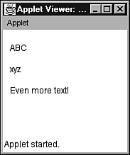
The drawBytes method draws text from all or part of an array of bytes. This method has the following signature: void drawBytes (byte [] text, int offset, int length, int x, int y) Specifically, the text contained in the byte array is drawn using the graphics context's current font and color. The first text character is located at text [offset] and the number of text characters is specified by length. The leftmost text character is located x pixels from the left edge of the drawing surface. The baseline of these text characters is located y pixels from the top edge of the drawing surface. Tip The capability to draw text from an array of bytes is useful when displaying files of information created by legacy programs. (Legacy programs typically use ASCII to store text.) When drawBytes is used to display this text, no conversion from ASCII to Unicode is required, which results in a performance boost. The drawChars method draws text from all or part of an array of characters. This method has the following signature: void drawChars (char [] text, int offset, int length, int x, int y) The text contained in the char array is drawn using the graphics context's current font and color. The first text character is located at text [offset] and the number of text characters is specified by length. The leftmost text character is located x pixels from the left edge of the drawing surface. The baseline of these text characters is located y pixels from the top edge of the drawing surface. Finally, the drawString method draws text from a String object. This method has the following signature: void drawString (String text, int x, int y) The text is drawn using the graphics context's current font and color. The leftmost text character is located x pixels from the left edge of the drawing surface. The baseline of these text characters is located y pixels from the top edge of the drawing surface. Listing 13.1 presents source code to the DrawTextDemo applet. This applet illustrates the text drawing methods. Listing 13.1 The DrawTextDemo Applet Source Code // DrawTextDemo.java import java.awt.*; import java.applet.Applet; public class DrawTextDemo extends Applet { public void paint (Graphics g) { byte [] barray = { 0x41, 0x42, 0x43 } ; char [] carray = { 'x', 'y', 'z'} ; String s = "Even more text!"; g.drawBytes (barray, 0, barray.length, 10, 30); g.drawChars (carray, 0, carray.length, 10, 60); g.drawString (s, 10, 90); } } Note Please refer to the previous chapter to learn how to execute an applet. The DrawTextDemo applet displays all text contained in barray, carray, and s on its drawing surface. The default font and color of graphics context g controls the appearance of this text. The y-coordinate of each baseline ”30, 60, and 90 ”is chosen so one line of text will not overwrite the next line. (A better mechanism to control the baseline's location will be presented when font metrics are discussed.) Figure 13.2 shows DrawTextDemo running in the Applet Viewer. Figure 13.2. The DrawTextDemo applet shows text displayed using a graphics context's text drawing methods. Caution Be careful when choosing the starting array index and length passed to either drawBytes or drawChars. Each method adds the length to the starting array index. If this sum is negative or equals/exceeds the length of the array, either an ArrayIndexOutOfBounds Exception object or a StringIndexOutOfBoundsException object will be thrown. (The same exceptions are thrown if the starting array index is negative or equals/exceeds the array's length.) Drawing ShapesMany graphics-based computer programs require various shapes to be drawn. For example, computer-assisted drafting programs (often referred to as CAD programs) make extensive use of lines and rectangles. The AWT's Graphics class provides methods for drawing several useful shapes. These shapes can be divided into the following categories:
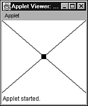
Lines and PointsIn addition to text, lines and points are probably the most commonly drawn entities. To accomplish this task, Graphics provides a method called drawLine. This method has the following signature: void drawLine (int x1, int y1, int x2, int y2) A line of pixels is drawn using the graphics context's current color. This line starts at ( x1, y1 ) and continues to ( x2, y2 ). However, a point is drawn instead of a line if x1 equals x2 and y1 equals y2. To illustrate drawing lines and points, Listing 13.2 presents source code to an applet called DrawLinePointDemo. Listing 13.2 The DrawLinePointDemo Applet Source Code // DrawLinePointDemo.java import java.awt.*; import java.applet.Applet; public class DrawLinePointDemo extends Applet { public void paint (Graphics g) { // Get the width and height of the applet's drawing surface. int width = getSize ().width; int height = getSize ().height; g.drawLine (0, 0, width 1, height 1); g.drawLine (0, height 1, width 1, 0); int centerX = width / 2; int centerY = height / 2; for (int row = -5; row < 5; row++) for (int col = -5; col < 5; col++) g.drawLine (centerX + col, centerY + row, centerX + col, centerY + row); } } The DrawLinePointDemo applet displays two intersecting diagonal lines on its drawing surface. A rectangular bull's-eye is drawn around this intersection. Figure 13.3 shows DrawLinePointDemo running in the Applet Viewer. Figure 13.3. The DrawLinePoint Demo applet shows lines and points displayed using a graphics context's drawLine method. Caution DrawLinePointDemo introduces a pair of for loops in its paint method to draw the bull's-eye. However, in most situations, loops should not be placed in paint. The reason for this restriction has to do with performance. A drawing surface's paint method is called whenever it needs updating. This can occur if the drawing surface was partially or completely covered by some other window and is now being made visible. If paint takes too long to execute, you'll notice a decrease in your program's performance. To be responsive , the paint method (or methods) should execute as quickly as possible. Large loops slow down this execution. RectanglesRectangles can be drawn by using the drawLine method. However, this is not necessary because Graphics provides several methods for drawing and filling various kinds of rectangles. Except for clearRect, each method draws either a solid rectangle or the outline of a rectangle using a graphics context's current color. These methods include
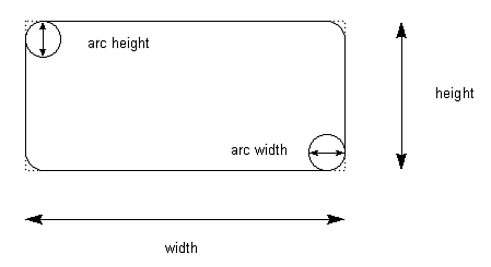
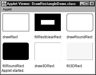
The drawRect method draws the outline of a rectangle. This method has the following signature: void drawRect (int x, int y, int width, int height) The rectangle is drawn with an upper-left corner located at ( x, y ) and a lower-right corner located at ( x + width, y + height ). In contrast, the fillRect method draws a solid rectangle. This method has the following signature: void fillRect (int x, int y, int width, int height) The rectangle is drawn with an upper-left corner located at ( x, y ) and a lower-right corner located at ( x + width “ 1, y + height “ 1 ). The filled rectangle is one pixel smaller to the right and bottom than requested . (This is standard practice for several rectangle and non-rectangle methods.) Note It might interest you to know that the practice of creating a filled rectangle, one pixel smaller to the right and bottom than requested, originated in drawing 3D objects with polygons (multi-sided shapes). The idea was to avoid drawing the same pixel twice, because many graphics routines place filled rectangles next to each other. The clearRect method draws a solid rectangle by filling it with the drawing surface's current background color. (This color is NOT the same as a graphics context's current color.) This method is commonly used to clear all pixels from a drawing surface, and has the following signature: void clearRect (int x, int y, int width, int height) The rectangle is drawn with an upper-left corner at ( x, y ), and a lower-right corner at ( x + width “ 1, y + height “ 1 ). The drawRoundRect method draws the outline of a rectangle with rounded corners. This method has the following signature: void drawRoundRect (int x, int y, int width, int height, int arcWidth, int arcHeight) The rectangle is drawn with an upper-left corner located at ( x, y ) and a lower-right corner located at ( x + width, y + height ). The horizontal diameter of each corner arc is specified by arcWidth and the vertical diameter of each arc is specified by arcHeight. Figure 13.4 illustrates a rounded rectangle with various dimensions, including height, width, and arc width/height diameters (for its rounded corners). Figure 13.4. A rounded rectangle's four corners have the same arc widths and the same arc heights. However, the arc width can differ from the arc height. The fillRoundRect method draws a solid rectangle with rounded corners. This method has the following signature: void fillRoundRect (int x, int y, int width, int height, int arcWidth, int arcHeight) The rectangle is drawn with an upper-left corner located at ( x, y ) and a lower-right corner located at ( x + width “ 1, y + height “ 1 ). The horizontal diameter of each corner arc is specified by arcWidth and the vertical diameter of each arc is specified by arcHeight. Tip The drawRoundRect and fillRoundRect methods can be used to draw circles or ellipses by making arcWidth the same as width and arcHeight the same as height. However, Graphics provides other methods better suited to this task. The draw3DRect method draws the outline of a rectangle with a 3D appearance. This method has the following signature: void draw3DRect (int x, int y, int width, int height, boolean raised) The rectangle is drawn with an upper-left corner located at ( x, y ) and a lower-right corner located at ( x + width, y + height ). The edges of the rectangle are highlighted so that they appear to be beveled and lit from the upper-left corner. The rectangle appears raised if raised is true or sunken if raised is false. If the current color is black, raised has no effect. Finally, the fill3DRect method draws a solid rectangle with a 3D appearance. This method has the following signature: void fill3DRect (int x, int y, int width, int height, boolean raised) Apart from drawing a solid rectangle with a 3D appearance (and the fact that the resulting rectangle is one pixel narrower and one pixel shorter), this method is basically the same as draw3DRect. Listing 13.3 presents source code to the DrawRectangleDemo applet. This applet illustrates the rectangle methods. Listing 13.3 The DrawRectangleDemo Applet Source Code // DrawRectangleDemo.java import java.awt.*; import java.applet.Applet; public class DrawRectangleDemo extends Applet { public void paint (Graphics g) { // Get the width and height of the applet's drawing surface. int width = getSize ().width; int height = getSize ().height; int rectWidth = (width 50) / 3; int rectHeight = (height 70) / 2; int x = 5; int y = 5; g.drawRect (x, y, rectWidth, rectHeight); g.drawString ("drawRect", x, rectHeight + 30); x += rectWidth + 20; g.fillRect (x, y, rectWidth, rectHeight); // Calculate a border area with each side equal to 25% of // the rectangle's width. int border = (int) (rectWidth * 0.25); // Clear 50% of the filled rectangle. g.clearRect (x + border, y + border, rectWidth 2 * border, rectHeight 2 * border); g.drawString ("fillRect/clearRect", x, rectHeight + 30); x += rectWidth + 20; g.drawRoundRect (x, y, rectWidth, rectHeight, 15, 15); g.drawString ("drawRoundRect", x, rectHeight + 30); x = 5; y += rectHeight + 40; g.fillRoundRect (x, y, rectWidth, rectHeight, 15, 15); g.drawString ("fillRoundRect", x, y + rectHeight + 25); x += rectWidth + 20; g.setColor (Color.yellow); for (int i = 0; i < 4; i++) g.draw3DRect (x + i * 2, y + i * 2, rectWidth - i * 4, rectHeight - i * 4, false); g.setColor (Color.black); g.drawString ("draw3DRect", x, y + rectHeight + 25); x += rectWidth + 20; g.setColor (Color.yellow); g.fill3DRect (x, y, rectWidth, rectHeight, true); g.setColor (Color.black); g.drawString ("fill3DRect", x, y + rectHeight + 25); } } The DrawRectangleDemo applet divides its drawing surface into six regions . A separate kind of rectangle is drawn in each region. For the rectangle created by fillRect, clearRect is used to clear 50% of this rectangle. Because a 3D rectangle's effects cannot be seen with a black color, DrawRectangleDemo changes the current color of its graphics context to yellow. Figure 13.5 shows DrawRectangleDemo running under Applet Viewer. Figure 13.5. The DrawRectangle Demo applet shows various kinds of rectangles displayed using a graphics context's rectangle methods. OvalsThere is a lot to be said for curved shapes. After all, cars wouldn't drive very well with rectangular wheels. A perfectly curved and closed shape is an oval. It is important to make a distinction between two kinds of ovals: circles and ellipses. A circle is an oval with a single center. This occurs when the oval's width and height are identical. An ellipse is an oval with two centers. If the width is greater than the height, a short and fat oval results. However, if the height is greater than the width, a tall and skinny oval results. Tip On some video displays, because of screen curvature, an oval might look like a circle when viewed in certain spots, and an ellipse when viewed in other spots. If you notice this behavior, try adjusting your video display's screen adjustment controls. Graphics provides a pair of methods for drawing ovals:
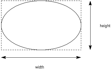
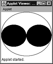
The drawOval method draws the outline of an oval. This method has the following signature: void drawOval (int x, int y, int width, int height) The outline is drawn, using the graphics context's current color, in an imaginary bounding rectangle. The upper-left corner of this rectangle is located at ( x, y ) and the lower-right corner is located at ( x + width, y + height ). Figure 13.6 illustrates an oval drawn in a bounding rectangle. Figure 13.6. An oval is drawn inside an imaginary bounding rectangle. The fillOval method draws a solid oval. This method has the following signature: void fillOval (int x, int y, int width, int height) The solid oval is drawn, using the graphics context's current color, in an imaginary bounding rectangle. The upper-left corner of this rectangle is located at ( x, y ) and the lower-right corner is located at ( x + width “ 1, y + height “ 1 ). Note There is no technical reason for the fillOval method filling a solid oval in a rectangular area one pixel smaller horizontally and vertically than the area defined by the drawOval method. In fact, the fillOval method could have been designed to draw from (x, y) to (x + width, y + height). However, because fillOval was designed to behave in a manner consistent with the other "fill" methods, it adopts the same behavior. To illustrate these methods, Listing 13.4 presents source code to the DrawOvalDemo applet. Listing 13.4 The DrawOvalDemo Applet Source Code // DrawOvalDemo.java import java.awt.*; import java.applet.Applet; public class DrawOvalDemo extends Applet { public void paint (Graphics g) { // Get the width and height of the applet's drawing surface. int width = getSize ().width; int height = getSize ().height; g.drawOval (0, 0, width 1, height 1); g.fillOval (0, width / 4, width / 2, height / 2); g.fillOval (width / 2, width / 4, width / 2, height / 2); } } The DrawOvalDemo applet displays an oval outline with two solid ovals inside this outline. Figure 13.7 shows DrawOvalDemo running in the Applet Viewer. Figure 13.7. The DrawOvalDemo applet shows ovals displayed using a graphics context's oval methods. ArcsAn arc is a piece of an oval. Graphics provides two methods for drawing arcs:
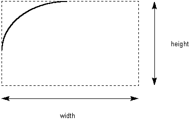
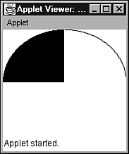
The drawArc method draws the outline of an arc. This method has the following signature: void drawArc (int x, int y, int width, int height, int startAngle, int endAngle) The outline is drawn, using the graphics context's current color, in an imaginary bounding rectangle. The upper-left corner of this rectangle is located at ( x, y ) and the lower-right corner is located at ( x + width, y + height ). The arc begins at startAngle and continues for arcAngle degrees. A startAngle of 0 degrees represents the three o'clock position. A positive arcAngle value causes the arc to be drawn in a counter-clockwise rotation, whereas a negative value causes the arc to be drawn in a clockwise rotation. Figure 13.8 illustrates an arc drawn in a bounding rectangle. Figure 13.8. An arc is drawn inside an imaginary bounding rectangle. The fillArc method draws a solid arc ”a pie-shaped wedge ”by filling all pixels from the arc to the origin of its bounding rectangle. This method has the following signature: void fillArc (int x, int y, int width, int height, int startAngle, int endAngle) The solid arc is drawn, using the graphics context's current color, in an imaginary bounding rectangle. The upper-left corner of this rectangle is located at ( x, y ) and the lower-right corner is located at ( x + width “ 1, y + height “ 1 ). Apart from the facts that a solid arc is being drawn and that the rectangle's lower-right corner is one pixel closer to the upper-left corner, fillArc behaves identically to drawArc. Listing 13.5 presents source code to a DrawArcDemo applet that illustrates these methods. Listing 13.5 The DrawArcDemo Applet Source Code // DrawArcDemo.java import java.awt.*; import java.applet.Applet; public class DrawArcDemo extends Applet { public void paint (Graphics g) { // Get the width and height of the applet's drawing surface. int width = getSize ().width; int height = getSize ().height; g.drawArc (0, 0, width, height, 0, 90); g.fillArc (0, 0, width, height, 90, 90); } } This applet displays an arc outline rotated counter-clockwise from three o'clock to twelve o'clock and a solid arc rotated counter-clockwise from twelve o'clock to nine o'clock. Figure 13.9 shows DrawArcDemo running in the Applet Viewer. Figure 13.9. The DrawArcDemo applet shows arcs displayed using a graphics context's arc methods. PolygonsComputer games (such as flight simulators) make extensive use of polygons (multisided shapes). Polygons are drawn by connecting line segments to a sequence of points laid out in some kind of path . There are two varieties of polygons: closed polygons and open polygons. A closed polygon has a line segment connecting the final point to the first point, whereas an open polygon does not have this connection. Graphics provides the following methods for drawing and filling polygons:
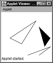
The drawPolyline method draws the outline of an open polygon. This method has the following signature: void drawPolyline (int [] xPoints, int [] yPoints, int numPoints) The xPoints and yPoints arrays identify coordinates of points that lie on the polygon's path. The number of points is identified by numPoints. The path is drawn, using the graphics context's current color, by connecting these points with line segments. The polygon is left open. The drawPolygon method draws the outline of a closed polygon. This method has the following signature: void drawPolygon (int [] xPoints, int [] yPoints, int numPoints) This method is identical to the previous method except that the polygon is automatically closed by drawing a line segment from the last point to the first point. The fillPolygon method draws a solid polygon. This method has the following signature: void fillPolygon (int [] xPoints, int [] yPoints, int numPoints) This method is identical to drawPolygon except that it also fills in the polygon's interior with the graphics context's current color. To illustrate polygons, Listing 13.6 presents source code to an applet called DrawPolygonDemo. Listing 13.6 The DrawPolygonDemo Applet Source Code // DrawPolygonDemo.java import java.awt.*; import java.applet.Applet; public class DrawPolygonDemo extends Applet { public void paint (Graphics g) { // Get the width and height of the applet's drawing surface. int width = getSize ().width; int height = getSize ().height; int [] xp1 = { 30, 120, 70 } ; int [] yp1 = { 90, 30, 110 } ; g.drawPolygon (xp1, yp1, xp1.length); int [] xp2 = { 90, 170, 130 } ; int [] yp2 = { 150, 120, 150 } ; g.drawPolyline (xp2, yp2, xp2.length); int [] xp3 = { 130, 170, 150 } ; int [] yp3 = { 50, 90, 120 } ; g.fillPolygon (xp3, yp3, xp3.length); } } The DrawPolygonDemo applet displays a pair of closed and open polygon outlines along with a filled polygon. Figure 13.10 shows DrawPolygonDemo running in the Applet Viewer. Figure 13.10. The DrawPolygon Demo applet shows polygons displayed using a graphics context's polygon methods. Caution Care is required when creating polygon arrays. If either array does not have numPoints elements, an ArrayIndexOutOfBoundsException object is thrown. Utility Classes and InterfacesThe AWT provides several utility classes and one interface that simplify working with graphics. These include
PointThe Point class (located in the java.awt package) encapsulates the coordinates of a point. This class is commonly used by methods that return a pair of coordinates. Table 13.2 presents Point 's fields and methods (except for a handful of overridden Java 2D methods) that are publicly accessible. Table 13.2. Inside the AWT's Point Class
DimensionThe Dimension class (located in the java.awt package) encapsulates the width and height dimensions of a shape. Table 13.3 presents Dimension 's fields and methods (except for a handful of overridden Java 2D methods) that are publicly accessible. Table 13.3. Inside the AWT's Dimension Class
RectangleThe Rectangle class (located in the java.awt package) encapsulates the coordinates and dimensions of a rectangular shape. Table 13.4 presents Rectangle 's fields and methods (except for a handful of overridden and implemented Java 2D methods) that are publicly accessible. Table 13.4. Inside the AWT's Rectangle Class
PolygonThe Polygon class (located in the java.awt package) encapsulates two arrays of point coordinates that connect the line segments comprising a polygon. Table 13.5 presents those fields and methods (except for a handful of implemented Java 2D Shape methods) that are publicly accessible. Table 13.5. Inside the AWT's Polygon Class
You've already seen some of Graphic 's polygon methods. However, there are two other methods specially designed for use with the Polygon class. These methods take a single Polygon argument, and have the following signatures: void drawPolygon (Polygon) void fillPolygon (Polygon) Listing 13.7 presents source code for the DrawPolygonDemo2 applet that demonstrates these methods. Listing 13.7 The DrawPolygonDemo2 Applet Source Code // DrawPolygonDemo2.java import java.awt.*; import java.applet.Applet; public class DrawPolygonDemo2 extends Applet { public void paint (Graphics g) { // Get the width and height of the applet's drawing surface. int width = getSize ().width; int height = getSize ().height; int [] xp1 = { 30, 120, 70 } ; int [] yp1 = { 90, 30, 110 } ; Polygon p = new Polygon (xp1, yp1, xp1.length); g.drawPolygon (p); p = new Polygon (); p.addPoint (90, 180); p.addPoint (180, 120); p.addPoint (130, 200); g.drawPolygon (p); int [] xp2 = { 130, 170, 150 } ; int [] yp2 = { 50, 90, 120 } ; g.fillPolygon (new Polygon (xp2, yp2, yp2.length)); } } ShapeThe Shape interface provides methods that are used by objects representing geometric shapes. With the exception of getBounds, these methods are designed to be implemented by Java 2D shapes. getBounds returns a Rectangle object whose upper-left corner coordinates and dimensions completely enclose a shape. (You might have noticed that Polygon and Rectangle have a getBounds method. This is no coincidence ; these classes implement Shape. ) Utility MethodsThe Graphics class provides a number of utility methods for accomplishing tasks related to drawing text and shapes. These tasks include
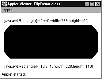
ClippingClipping is the technique of restricting graphics drawing to a specific region on a drawing surface. Usually, this region has a rectangular shape, although nonrectangular shapes are also possible (with Java 2D). Graphics provides several methods for defining and determining clipping regions. These methods include
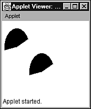
The clipRect method reduces the clipping region to the intersection of the current clipping region and its argument values. You can never enlarge the clipping region. This method has the following signature: void clipRect (int x, int y, int width, int height) The desired clip rectangle has an upper-left corner located at ( x, y ), and a lower-right corner located at ( x + width - 1, y + height - 1 ). However, if the current clip rectangle is smaller, the new clip rectangle will be the intersection of this rectangle and the desired clip rectangle. If no previous clip rectangle was established, the new clip rectangle will be the desired clip rectangle. The getClipBounds method returns a Rectangle object containing the bounds of the current clip rectangle. This method has the following signature: Rectangle getClipBounds () The setClip method sets the clipping region to the intersection of the current clipping region and its argument values. This method has the following signature: void setClip (int x, int y, int width, int height) The desired clip rectangle has an upper-left corner located at ( x, y ), and a lower-right corner located at ( x + width - 1, y + height - 1). Graphics provides a variation of setClip that takes a single argument. This argument is an object whose class implements the Shape interface. The alternate setClip has the following signature: void setClip (Shape clip) The clipping region is restricted to that specified by clip. For non-Java 2D work, the object implementing Shape must be of type Rectangle. The getClip method returns an object that implements the Shape interface and specifies the clipping region. This method has the following signature: Shape getClip () Listing 13.8 presents source code to a ClipDemo applet that demonstrates clipping. Listing 13.8 The ClipDemo Applet Source Code // ClipDemo.java import java.awt.*; import java.applet.Applet; public class ClipDemo extends Applet { public void paint (Graphics g) { g.drawString (g.getClipBounds ().toString (), 10, 30); g.clipRect (10, 40, getSize ().width 20, getSize ().height 80); g.fillOval (0, 0, getSize ().width, getSize ().height); String newClip = g.getClipBounds ().toString (); g.setClip (0, 0, getSize ().width, getSize ().height); g.drawString (newClip, 10, getSize ().height 10); } } The ClipDemo applet displays a pair of text strings and a clipped oval. These strings represent the contents of Rectangle objects returned from calls to getClipBounds. In essence, they show the size of the clip region before and after a clip rectangle is established. Figure 13.11 shows Applet Viewer running ClipDemo. Figure 13.11. The ClipDemo applet shows the results of using a graphics context's clipping methods. Copying RegionsSometimes, you might want to copy a region of graphics from one area on the drawing surface and paste this copy to another area (perhaps for tiling or scrolling purposes). To simplify this task, Graphics provides the copyArea method. This method has the following signature: void copyArea (int x, int y, int width, int height, int dx, int dy) The region to be copied is bounded by an upper-left corner at ( x, y ) and a lower-right corner at ( x + width, y + height ). This region is copied to a target area with an upper-left corner at ( x + dx, y + dy ) and a lower-right corner at ( x + width + dx, y + height + dy ). The target area can lie partially/completely outside the clipping region. Listing 13.9 presents source code to a CopyDemo applet that demonstrates copying regions. Listing 13.9 The CopyDemo Applet Source Code // CopyDemo.java import java.applet.*; import java.awt.*; public class CopyDemo extends Applet { public void paint (Graphics g) { g.fillArc (5, 15, 50, 75, 25, 165); g.copyArea (5, 15, 50, 75, 50, 50); } } The CopyDemo applet draws a solid arc and copies this region to another area on the drawing surface. Figure 13.12 shows CopyDemo running in the Applet Viewer. Figure 13.12. The CopyDemo applet shows the results of using a graphics context's copyArea method. Selecting Drawing ModesNormally, when you draw a shape over a previously drawn shape, the new shape's pixels completely replace the old shape's pixels. This default drawing mode is known as paint mode. However, there is an alternate mode that you can use: XOR mode. XOR mode dates back several years to a time when it was commonly used to achieve animation. This is how it works: When XOR mode is in effect, whatever shape is drawn changes the background colors to something quite different. Then, when the same shape is drawn a second time, the original background colors are restored. (This mode works by exclusive ORing pixel color values on the binary digit level. Repeating the same operation twice in a row restores the original color.) Nowadays, XOR mode is often used to draw the selection rectangle in painting programs. This rectangle (which is typically displayed with a dashed or dotted outline) is drawn over the background, to show the portion of a drawing that has currently been selected. XOR mode is used to draw (and later remove) this rectangle. When the rectangle is removed, that part of the drawing hidden by the rectangle is restored, thanks to XOR mode. Graphics provides a pair of methods for switching to either paint mode or XOR mode:
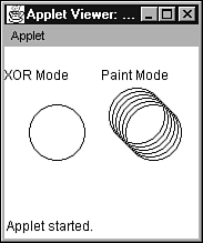
The setPaintMode method switches the drawing mode to paint mode. Because paint mode is the default drawing mode, you would only use this method to switch from XOR mode back to paint mode. This method has the following signature: void setPaintMode () In contrast, the setXORMode method switches the drawing mode to XOR mode, and has the following signature: void setXORMode (Color c) Color argument c is known as an XOR color. This color is usually the drawing surface's background color, but it can be any color. For each subsequently drawn pixel, the XOR color will be XORed with the color of the pixel being overwritten and the graphics context's current color. Listing 13.10 presents source code to an applet called ModeDemo that demonstrates paint and XOR modes. Listing 13.10 The ModeDemo Applet Source Code // ModeDemo.java import java.awt.*; import java.applet.Applet; public class ModeDemo extends Applet { public void paint (Graphics g) { int w = getSize ().width; int h = getSize ().height; int midW = w / 2; g.drawString ("Use XOR", 0, 30); g.drawOval (7, 37, 50, 50); g.setXORMode (Color.white); for (int i = 0; i < 15; i += 3) { g.drawOval (10 + i 3, 40 + i 3, 50, 50); g.drawOval (10 + i, 40 + i, 50, 50); } g.setPaintMode (); g.drawString ("No XOR", midW, 30); g.drawOval (midW + 7, 37, 50, 50); for (int i = 0; i < 15; i += 3) { g.drawOval (midW + 10 + i 3, 40 + i 3, 50, 50); g.drawOval (midW + 10 + i, 40 + i, 50, 50); } } } When you run ModeDemo, you'll see the applet's drawing surface divided into two halves: Both halves display identical sequences of circles. However, because the left half uses XOR mode, only the final circle in this sequence is displayed. In contrast, the right half uses paint mode, and displays the entire sequence. Figure 13.13 shows ModeDemo running in the Applet Viewer. Figure 13.13. The ModeDemo applet divides its drawing surface into two halves, with the left half demonstrating XOR mode and the right half demonstrating paint mode. |
EAN: 2147483647
Pages: 353
