49.
3.2 CAD Tools for Multilevel Logic Synthesis
We can obtain minimized two-level logic networks from the canonical sum of products or product of sums form, by applying the appropriate reduction methods(K-maps, Quine-McCluskey, a two-level logic minimizer like espresso, etc.). Signal propagations can be fast, because no signal has to travel through more than two gate levels (not counting zeroth-level inversions). The drawback is the potential for large gate fan-ins, which can reduce gate performance and increase circuit area in some technologies. In many technologies, including TTL, gates with more than four inputs are rare, if they exist at all. In a practical gate-level realization of a network, the large fan-in gates must be replaced by a multiple-level network of smaller fan-in gates. This has motivated much recent interest in multilevel logic synthesis.3.2.1 General Concept
An optimal two-level network is one that uses the smallest number of product terms and literals to realize a given truth table. It is not so easy to define optimality for multilevel networks. Is the network optimal if it has the smallest number of gates? Or is it more critical to have the fewest literals in the resulting expression? Hence, the process with multilevel systems is called synthesis rather than optimization. The goal is to create or "synthesize" a reasonable multilevel implementation, without any pretense that the result is the best that is possible.The synthesis process involves two steps. The first, technology-independent stage factors out common sublogic to reduce gate fan-ins, increasing the number of gate levels as a side effect. This step is independent of the kinds of gates that will eventually be used to implement the network. It works by exploiting basic mathematical properties of Boolean expressions.
The second, technology-dependent stage maps the resulting factored Boolean equations into a particular implementation using a library of available gates. For example, if only 2-input OR gates are found in a particular library, then a 4-input OR gate would have to be mapped into three 2-input OR gates
(see Figure 3.16). 
Such reorganizations of the logic network can introduce additional levels of logic in the function's implementation, possibly affecting the delay through the circuit.
3.2.2 Factored Forms and Operations
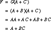
Multilevel synthesis systems place Boolean expressions in a special "tree-structured" form and perform special operations on these forms. We introduce them in this subsection.Factored Form The multilevel synthesis system places an expression into a factored form. Simply stated, this is an expression that alternates between AND and OR operations, a kind of "sum of products of sums of products." The following function is in factored form
Examining the expression, we see that no further subexpressions can be factored out. For the purpose of counting literals, the factored form for X can be rewritten as a sequence of two-level expressions:![]()
The structure of the expression is a little clearer if it is represented in the form of a graph or tree, where the "leaves" represent literals and the internal nodes represent either an AND or OR operation. This graphical representation is shown in Figure 3.17.
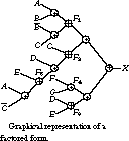
For the most part, the ANDs and ORs alternate between adjacent nodes of the tree.
Criterion for Multilevel Simplification In modern VLSI technologies, de-signers have observed that gates (internal nodes of the graph of Figure 3.17) require relatively little circuit area but connections (arcs of the graph) use significant area. Even for the modest levels of circuit integration available in TTL, the complexity of a circuit realization is strongly related to the number of wires used in its construction. Because the number of internal connections tends to scale with the number of literals, most multilevel logic synthesis systems attempt to minimize the number of literals. The literal count is based on the multilevel expression written as a sequence of two-level expressions. For the function depicted in Figure 3.17, for example, the literal count is 18. Note that when they are referenced in expressions, the functions F1, F2, F3, F4, and F5 count as literals.
No procedure for multilevel simplification guarantees, like the Quine-McCluskey algorithm for two-level logic, that it will derive an optimal multilevel network. With a two-level minimizer like espresso, it is possible to specify the equations, run the program, and simply examine the result. Not so with multilevel synthesis systems. Rather than follow a precise algorithm, these systems provide a rich set of operations to manipulate the logic network. Normally you would apply the operations to the network interactively, although standard "scripts" have been developed that achieve good results. You do not need a deep understanding of the underlying operations to use these scripts.
The basic operations for manipulating a multilevel network are (1) decomposition, (2) extraction, (3) factoring, (4) substitution, and (5) collapsing. In the following sections, we will describe each of these operations and illustrate it with a simple example.
Decomposition Decomposition takes a single Boolean expression and replaces it by a collection of new expressions. Consider the function![]()
This expression is in reduced sum of products form and has 12 literals. It requires nine gates, counting inverters, for implementation (see Figure 3.18(a)).
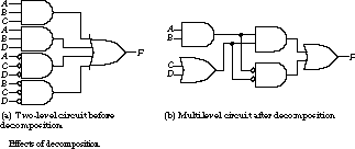
However, the expression can be decomposed into two much simpler functions:![]()
The resulting set of functions has eight literals and requires seven gates for implementation (see Figure 3.18(b))-nothing is free, though, and the number of gate levels has increased from two to three.
Let's look at an example of extraction. We start with the functions
Note that the extraction operation does not require the functions to begin in a two-level form.
In this example, the extraction operation discovers that the sub-ex-pressions X = (A + B) and Y = (CD) are common to F, G, and F, H, respectively. These subexpressions are called primary divisors or, more technically, kernels and cubes. Reexpressed in these terms, the functions can be rewritten as

The original collection of functions contains 11 literals and requires eight gates for implementation.
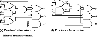
(In Figure 3.19(a), the bubble at the input of the gate that computes G counts as one inverter gate.) The revised set of functions, after extraction, still contains 11 literals but now needs only seven gates for its implementation. You can see in Figure 3.19(b) that the single-level implementation for H has been replaced by a two-level implementation after extraction. The number of gates is reduced, but the function H now incurs worse delay.
Factoring Factoring takes an expression in two-level form and reexpresses it as a multilevel function without introducing any intermediate subfunctions. It can be used as a preliminary step before extraction, to identify potential common subexpressions.
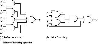
As an example, let's consider the following function in sum of products form. It has nine literals and can be implemented with five gates (Figure 3.20(a)):![]()
After factoring, the number of literals is reduced to seven:
This can be implemented with four gates (Figure 3.20(b)).
Substitution Substituting a function G into a function F reexpresses F in terms of G. For example, if ![]() , and
, and ![]() , then F can be rewritten in terms of G as follows:
, then F can be rewritten in terms of G as follows:
Once common subexpressions have been identified, substitution can be used to reexpress functions as factored forms over the subexpressions.
Collapsing Collapsing is the reverse of substitution. It might be used to reduce the number of levels of logic to meet a timing constraint. As an example, we can collapse G back into F:
The number of literals used to express F has been reduced from five to three.
Polynomial Division and Multilevel Factoring All of the multilevel operations have strong analogies with the multiplication and division of polynomials. The strategy is to rewrite the expression for a function F in terms of the subexpressions P, Q, and R, which represent the divisor, quotient, and remainder, respectively. In generic terms, F is written as![]()
As a more concrete example, given the two expressions:
We could write X "divided" by Y as follows:
The divisor is Y = (A + B), the quotient is (C + D), and the remainder is E. Expanding the expression with the distributive law would yield the original equation for X.
Finding divisors is a rather difficult problem when the laws of Boolean algebra are considered. Multiplying Boolean expressions can yield unusual results because of the variety of simplification theorems you can apply. For example, consider the functions F and G:
Under the normal rules of algebra, G does not divide into F. The so-called algebraic divisors of F are D and (A + BC). That is, F can be divided by D, leaving the quotient A + BC with remainder E. It can also be divided by A + BC, leaving D as the quotient and E as the remainder.
However, if we apply the rules of Boolean algebra, then G does divide into F. We can write the quotient of F divided by G as![]()
This is because F can be rewritten as
The existence of Boolean divisors greatly increases the number of potential factorings of a set of expressions. Many optimization systems restrict themselves to the easier-to-find algebraic factors.
It should be clear from this discussion that the challenge in multilevel logic synthesis is to develop algorithms that can find good divisors. These lead to factored expressions with the greatest number of common subexpressions. By factoring out these subexpressions, we can minimize the number of literals needed to express a collection of functions. Extensive heuristics, beyond the scope of our discussion here, have been developed to identify good divisors.
3.2.3 A Tool for Multilevel Synthesis: MisII
MisII is a tool developed at the University of California at Berkeley to assist in performing multilevel synthesis. You must interact with misII to accomplish the synthesis. The complete range of operations it supports is beyond the scope of this text, but we will examine a useful subset that can be used to rearrange expressions into multilevel forms. Although the best results can be obtained by working with misII in its interactive mode, some carefully crafted standard scripts of misII operations, developed by experts, are available for novice designers.Example A Session with MisII Let's look at an example session with misII. In the following sequence of operations, we will (1) read a file containing Boolean equations that describe the combinational network to be manipulated (it is also possible to describe the network as a truth table, using espresso input format), (2) initially perform a two-level simplification (misII actually uses espresso as a subroutine), (3) decompose the resulting functions into a multilevel network, and (4) map the decomposed network onto the gates of a given gate library.The following sequence of commands reads in the equations that describe the sum and carry-out
(co) functions of the full adder from a standard text file, prints out the network in two-level form, and then prints out the network in its factored form: % misIIUC Berkeley, MIS Release #2.1 (compiled 3-Mar-89 at 5:32 PM)
misII> re full.adder
misII> p
{co} = a b ci + a b ci' + a b' ci + a' b ci
{sum} = a b ci + a b' ci' + a' b ci' + a' b' ci
misII> pf
{co} = a b' ci + b (ci (a' + a) + a ci')
{sum} = ci (a' b' + a b) + ci' (a b' + a' b)
The first line requests misII to read an equation file named full.adder. The p command prints out the network in two-level form. The pf command prints the network in a factored form.
The next sequence performs a two-level simplification. We then print out the results in two-level and factored forms:
misII> sim1 *misII> p
{co} = a b + a ci + b ci
{sum} = a b ci + a b' ci' + a' b ci' + a' b' ci
misII> pf
{co} = ci (b + a) + a b
{sum} = ci (a' b' + a b) + ci' (a b' + a' b)
The command sim1 requests misII to simplify the network using espresso as a two-level minimizer. The * tells misII to apply simplification to each node in the network in turn. You can see the results by typing p and pf.
Next, we ask misII to perform a good decomposition on all of the nodes of the network and then print out the result:
misII> gd *misII> pf
{co} = a [2] + b ci
{sum} = a' [3]' + a [3]
[2] = ci + b
[3] = b' ci' + b ci
The gd command is how you request a "good decomposition." MisII -generates potential factors and chooses those that will most reduce the number of literals. A quick decomposition, specified by qd, is faster, but the quality of the result is usually not as good. MisII comes up with a three-level network, with the subexpressions (ci + b) and (b' ci' + b ci) factored out. The simplified two-level network has 18 literals; the multilevel network has only 14 literals.
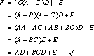
So far, the manipulations are technology independent. If we were to implement the network in terms of arbitrary input AND and OR gates, we would stop right here. However, misII has the ability to map the expressions onto the gates of a predefined gate library. We make use of a library of frequently used gates developed at Mississippi State University (see Figure 3.21 for a listing of some of the available gates), which is distributed with the misII software:
misII> rlib msu.genlibmisII> map
misII> pf
[361] = b' ci' + a'
[328] = b'
[329] = ci'
{co} = [328]' [329]' + [361]'
[3] = b ci' + b' ci
{sum} = [3] a' + [3]' a
misII> pg
[361] 1890:physical 32.00
[328] 1310:physical 16.00
[329] 1310:physical 16.00
{co} 1890:physical 32.00
[3] 2310:physical 40.00
{sum} 2310:physical 40.00
misII> pat
... using library delay model
{sum} : arrival=( 2.2 2.2)
{co} : arrival=( 2.2 2.2)
[328] : arrival=( 1.2 1.2)
[361] : arrival=( 1.2 1.2)
[329] : arrival=( 1.2 1.2)
[3] : arrival=( 1.2 1.2)
ci : arrival=( 0.0 0.0)
b : arrival=( 0.0 0.0)
a : arrival=( 0.0 0.0)
misII> quit
%
The command rlib msu.genlib makes the contents of this library known to misII, while the map command maps the current network onto the gates of the specified library. If the network is now printed with pf, the structure has been changed to reflect the available gate primitives. This is made a little more obvious by using the print gates command, or pg. The internal nodes of the network are described in terms of the gates chosen for their implementation, identified by the gate number as shown in Figure 3.21.
In this case, misII has chosen inverters (1310), XORs (2310), and OR-AND-Invert gates (1890) to implement the functions. The numbers following the word "physical" describe the relative size of these gates, so you can see that XORs require considerably more area than inverters: 40 units versus 16.
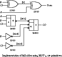
Figure 3.22 depicts the implementation of the full adder in terms of these gate primitives. The figure shows the gate numbers and internal node numbers. Recall that ![]() by DeMorgan's theorem, so the OR-AND-Invert gate and the Invert-AND-OR gate are really the same.
by DeMorgan's theorem, so the OR-AND-Invert gate and the Invert-AND-OR gate are really the same.
The pat command prints an estimate of the arrival of signals at various nodes of the network. A simple unit delay model is used. The model charges each circuit node with 1 time unit for each gate level plus 0.2 time unit for each gate fan-out. Because the sum and co outputs are two levels away from the inputs and the first-level gates fan out to only a single input, the model expects the outputs to change within 2.2 delay units of the input changes.
Examples More Multilevel Logic Manipulations It takes considerable skill and experience with the logic manipulation operations we have described to achieve good multilevel designs. Fortunately, experts in multilevel logic design have developed generic scripts of operations that can be used to good effect even by novice logic designers. We will see how well misII does in our combinational logic circuit case studies: the full adder, the 2-bit adder, and the BCD increment by 1 circuit.
MisII is distributed with several different scripts. Throughout this section we will use a particular technology-independent script called, appropriately enough, "script." To invoke misII in a noninteractive mode, reading its commands from a text file, type the following:
misII -f script -t pla <espresso truth table file>
The -f parameter is followed by the name of a file containing misII commands. The -t pla parameter tells misII that the circuit description is in an espresso truth table format. The parameter is followed by the name of the file containing the truth table description.
Running misII against the full adder truth table yields the following output in BLIF (Berkeley Logic Interchange Format), a standard language for describing multilevel logic functions:
.model full.adder
.inputs a b ci
.outputs sum co
.names a b ci co sum
1--0 1
-1-0 1
--10 1
111- 1
.names a b ci co
11- 1
1-1 1
-11 1
.end
Each .names section describes a single output function. The first section describes Sum in terms of A, B, CI (carry in), and CO (carry out). The latter is defined in the second section as a function of A, B, and CI. In terms of Boolean algebra, the multilevel equations for Sum and CO are as follows:
![]()
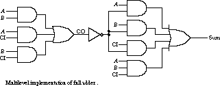
The expression for CO is identical to the one derived by espresso. How-ever, the expression for Sum is quite different. Let's look at this in more detail.
Recall that the full adder Sum is ![]() . The generic misII script we are using cannot make use of XOR gates. Expressed in sum of products form, Sum becomes
. The generic misII script we are using cannot make use of XOR gates. Expressed in sum of products form, Sum becomes ![]() . The misII expression for Sum, by using
. The misII expression for Sum, by using ![]() , effectively reduces the number of literals from 12 to 9. There is an obvious performance penalty, however. The two-level expression for Sum in the standard sum of products form has been replaced by a five-level expression
, effectively reduces the number of literals from 12 to 9. There is an obvious performance penalty, however. The two-level expression for Sum in the standard sum of products form has been replaced by a five-level expression (see Figure 3.23).
Our second example is the 2-bit binary adder. Recall that the inputs are two 2-bit binary numbers to be summed, represented by the inputs A, B and C, D, respectively. The output is a 3-bit binary number X, Y, Z. The misII output is as follows:
.model 2bit.adder
.inputs a b c d
.outputs x y z
.names a c z [22] x
---1 1
11-- 1
-10- 1
.names a b c d x z [22] y
1---0-- 1
--1---1 1
-11-0-- 1
--110-- 1
---100- 1
.names a b c d z
-0-1 1
-1-0 1
0-10 1
.names a d z [22]
110 1
.end
You can see that there are four .names sections, even though the function has three outputs. MisII has introduced a single new intermediate result, denoted by [22]. Outputs X and Y have been expressed as functions of Z and the new intermediate function [22] (Y is also a function of X):

This solution represents considerable savings of literals compared to the solution we found in Chapter 2. In sum of products form, X required 8 literals, Y used 22, and Z was expressed in 4, a total of 34. The multilevel implementation described above uses only 28 literals! Of course, there are performance implications of the multilevel implementation. The worst-case delay in the sum of products form is two gate levels, not counting inverted literals. In the multilevel form, it is eight gate levels (see Figure 3.24).

Our last example is the BCD increment by 1 function. The misII output looks like this:
.model bcd.increment
.inputs a b c d
.outputs w x y z
.names a b c d z w
1---1 1
0111- 1
.names a b c w z x
01-0- 1
0-100 1
.names a c z y
-11 1
000 1
.names a b c d z
0--0 1
-000 1
.end
This leads to the following collection of equations:

W and Y are functions of Z. X is a function of W and Z. The collection of functions is implemented with 23 literals. The schematic is shown in Figure 3.25.
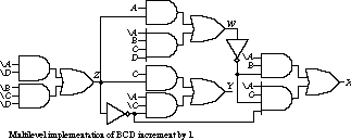
Worst-case delay is seven gate levels, not counting zeroth level inversions.
3.2.4 Summary
Our purpose in this section was to give you a flavor of the approaches to multilevel logic synthesis. The key idea is to identify common Boolean subexpressions across a collection of equations. If we can factor these out and share them among several functions, we can reduce the total number of literals needed to realize the functions. Fewer literals mean fewer wires, an important criterion in determining the complexity of a circuit.We introduced the basic operations for manipulating multilevel networks: decomposition, extraction, factoring, substitution, and collapsing. A powerful system for multilevel logic manipulation, called misII, was introduced, and we showed how it could process these operations to simplify the full adder network.
Because it takes a sophisticated designer to use misII to best effect in its interactive mode, we also showed how it could be used in a batch mode, with prespecified scripts, to do a reasonable job of deriving technology-independent multilevel implementations. The key is to reduce literal counts, although this usually has the effect of increasing the number of levels of gates.
We applied misII and its generic script to the full adder, the 2-bit binary adder, and the BCD increment by 1 circuit. We were able to reduce the literal counts from the two-level implementations, although the worst-case gate delays were substantially increased. These multilevel realizations will require less circuit area, but they will not be as fast as the two-level implementations.
[Top] [Prev] [Next]