34.
12.2 Time State (Divide and Conquer)
The classical approaches for implementing finite state machines yield a monolithic implementation that is sometimes unwieldy and difficult to change. An alternative approach, based on a divide-and-conquer strategy, partitions the single finite state machine into several simpler communicating state machines.12.2.1 Partitioning the State Machine
A common partitioning is to divide the controller into three state machines: the time state finite state machine, the instruction state finite state machine, and the condition state finite state machine. The time state finite state machine determines the current phase of instruction interpretation. These phases include instruction fetch, instruction decode, and instruction execute.The instruction state finite state machine identifies the current instruction being executed, such as load, store, add, or branch. It handles the process of instruction decoding.
The condition state finite state machine represents the state of the current condition of the data-path. In our example processor, the only interesting condition is the high-order bit of the AC. Other possible data-path conditions include whether the last ALU operation resulted in a zero, an overflow, or an underflow.
The partitioning into these three kinds of state machines is advantageous because there are usually only minor differences among the control sequences for different instructions. If these sequences are suitably parameterized, we can avoid a unique sequence for each instruction. Given that the instruction state can be readily decoded from the IR and the condition state from the data-path, we can even reduce the number of states in the overall finite state machine.
12.2.2 Time State Machines for the Example Processor
We start with the Moore state diagram of Figure 12.1. To obtain the time state finite state machine, we must look for the worst-case path through the classical state diagram. In the example processor, the worst-case path is eight states long(ADD or LOAD).Given this eight-state sequence, the idea is to parameterize the basic sequence by the outputs of the instruction state
(LD, ST, ADD, BRN) and the condition state (the high-order bit of the AC: AC 0, AC < 0) finite state machines. These outputs are associated with the transitions in the time state finite state machine. Under the appropriate conditions, the time state finite state machine will advance to its next state. The parameterized time state finite state diagram is shown in Figure 12.10.
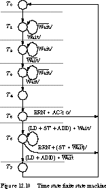
The instruction state and condition state finite state machines are given in Figure 12.11. We handle Reset by another state machine that is not shown. Every instruction, regardless of type, sequences through the first five states, IF0 through IF3 and OD. These are assigned to time states T0 through T4, respectively.
After this, the instructions follow different execution paths. Fortunately, much of this sequencing is still common. The states LD0-LD2, ST0, ST1, AD0-AD2, and BR0, BR1 have been collapsed onto the time states T5, T6, and T7. The only output from the time state machine is its current state, T0 through T7.
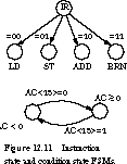
Figure 12.10 also shows how outputs from the instruction state and condition state machines influence the next-state sequencing in the time state finite state machine. For example, in time state T5, if the instruction is BRN and the AC 0, the time state machine returns to state T0. Otherwise, it advances to state T6. This quick return to the beginning of the time state machine is called a short-circuit transition. Although we could force all instructions to sequence through to T7 before returning, this would be less efficient because every instruction would have to take as many cycles as the longest possible instruction.
As another example, let's consider time state T6. If the instruction is LD, ST, or ADD and Wait is asserted, the machine stays in T6. If the instruction is BRN or ST with Wait unasserted, the machine returns to T0. Otherwise it advances to T7.
Generation of Microoperations It is not difficult to generate the micro-operation outputs from the time state, condition state, and instruction state. The various register transfer operations are asserted under the following conditions:
- 0 --> PC: Reset
- PC
+1 --> PC: T0- PC --> MAR: T0
- MAR --> Memory Address Bus: T2
+T6(LD+ST+ADD)- Memory Data Bus --> MBR: T2
+T6(LD+ADD)- MBR --> Memory Data Bus: T6 ST
- MBR --> IR: T4
- MBR --> AC: T7 LD
- AC --> MBR: T5 ST
- AC
+MBR --> AC: T7 ADD- IR<13:0> --> MAR: T5
(LD+ST+ADD)- IR<13:0> --> PC: T6 BRN
- 1 --> Read/
 : T2
: T2 +T6(LD+ADD)- 0 --> Read/
 : T6 ST
 - 1 --> Request: T2
+T6(LD+ST+ADD) - PC
Discussion In general, the time state approach can reduce states and simplify the next-state logic, at the possible expense of introducing more flip-flops. The short-circuit technique makes the next-state logic somewhat more complex but allows short cycle count instructions to finish early. This has the effect of leading to faster program execution.
[Top] [Next] [Prev]