INFRASTRUCTURE DESIGN: MODULAR BUILDING BLOCKS
| | ||
| | ||
| | ||
Designing the network infrastructure for on-demand access involves selecting the right modular components to meet requirements and then connecting them together in a cost-effective and efficient manner. This three-tiered infrastructure ( core , distribution, and access) can be developed one layer at a time, as long as standards-based components are used and the access methods are known. Figure 6-2 shows common symbols used for network design diagrams.
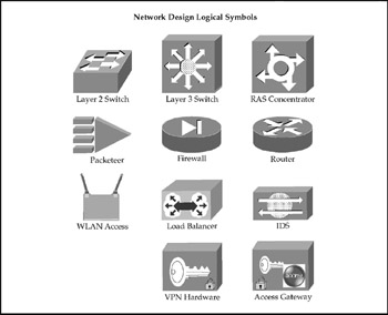
Figure 6-2: Network design logical symbols
Core Layer
The network core for a on-demand access network is typically a collapsed backbone that aggregates true "core" components (high-speed switching) and the access and distribution layer elements supporting the Citrix farm into a single platform or several similar platforms.
The core should be a Layer 3switched backbone designed to be redundant, expandable, and fast. The core can be either Layer 2 or Layer 3, with Layer 3 preferred due to faster convergence in response to failures (Layer 3 cores rely on routing table convergence, which takes only seconds, while Layer 2 cores rely on STP, which can take 3040 seconds or longer).
High-end Layer 3 core devices are chassis-based Layer 3 switches with redundant Layer 2 (switching) and Layer 3 (routing) components. For smaller networks, similar nonredundant fixed-configuration devices are widely available. Specifically, the network core should provide
-
– Layer 3 TCP/IP switching. The ability to transport IP packets across the core at "wire" (gigabit) speeds by rewriting packet headers, as opposed to routing packets individually. Some switches support a limited (slower) ability to handle IPX/SPX packets at Layer 3. NetBEUI is not supported at Layer 3 and must be bridged at Layer 2.
-
– Layer 2 "cut-through" switching. The ability to transport Layer 2 frames across the core without excessive buffering or processing. Low-end and older switches use slower switching methods such as store-and-forward and are unsuitable as core devices.
-
– Support for virtual LANs (VLAN) to segment traffic and separate groups of servers, Layer 2 server and user segments, and connections to other access or distribution layer devices.
-
– Support for Fast Ethernet and Gigabit Ethernet.
-
– Built-in support for network performance monitoring and management.
-
– Support for link aggregation using fast ether channel (FEC) or Gigabit Ether -Channel (GEC) technology via the Port Aggregation Protocol (PAgP) or the 802.3ad Link Aggregation Control Protocol (LACP).
-
– Support for advanced routing protocols (EIGRP, OSPF, IS-IS, BGP).
-
– Support for router redundancy protocols (HSRP, VRRP) at Layer 3 and path redundancy at Layer 2 paths (Spanning Tree Protocol [STP]) with fast convergence.
-
– Incremental growth capacity via additional modules or additional devices.
-
– High capacity nonblocking backplane. Typical high-end chassis-based solutions offer 64 Gbps or higher capacity, while fixed configuration low-end solutions provide 1020 Gbps.
Because of the complexity and variability, network diagrams of "core" layer topologies are included only in the complete network diagrams in the final section of this chapter.
Distribution Layer
The distribution layer provides aggregation of connections to groups of users and is generally categorized as either a LAN distribution point (connected to client access layer switches or media) or a WAN distribution layer (connecting to remote sites and services, to include the Internet). Distribution layer hardware usually consists of Layer 3 switches for large corporate or campus LANs and routers for WAN aggregation. In smaller networks, the core and distribution layers can be collapsed onto a single Layer 3 device. Distribution layer topologies are included only in the complete network diagrams in the final section of this chapter.
The distribution layer may include QoS, bandwidth management, and limited security enforcement (firewall, packet inspection, or access list filtering). Specific distribution layer hardware and media should be determined by the type and number of access layer connections required. In the case of enterprise-class distribution layer hardware, on-board (in the chassis) or in-line (separate appliance form-factor) IDS/IPS services should be included in the design.
Connections between the distribution layer and the core should be Layer 3 to allow for policy and security enforcement and to isolate broadcast traffic. Connectivity between distribution aggregation points and the core typically employs multiple VLANs using Fast Ethernet or Gigabit Ethernet.
Access Layer
Access layer building blocks are the most variable modular building blocks. The typical campus or corporate network requires multiple types to meet specific media connectivity and access method needs. The complement of access layer modules will determine the size and nature of most distribution layer devices. For remote sites and Internet connectivity, the access layer also provides the real security perimeter (firewall, proxy servers, and so on). As with the enterprise distribution layer, access layer devices at all ingress/egress points are the optimal location for IDS/IPS enforcement.
LAN Access Module
LAN access components are usually Layer 2 Fast Ethernet switches in campus wiring closets. These switches may have redundant Layer 2 uplinks to a Layer 3 distribution switch (large networks) or uplink directly to the Layer 3 core (smaller networks). Modern designs use single or multigigabit aggregated uplinks configured as 802.1q VLAN trunks (see Figure 6-3). Each trunk consists of one or more Gigabit Ethernet connections, each carrying multiple virtual LANs (one for marketing, one for sales, one for engineering, and so on). Access layer switches share many of the common characteristics of distribution and core switches including management, cut-through switching, Layer 2 aggregation, 802.1p Class of Service (CoS) tagging, and so forth.
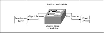
Figure 6-3: Typical LAN access module
WLAN Access Module
Despite security concerns, wireless local area networks (WLANs) have become ubiquitous throughout organizations today and as such are a critical part of most networks. WLAN-based IDS/IPS services should be employed on all WLAN devices such as access points and bridges where possible. When this is impractical , IDS/IPS should be placed in-line between the WLAN and the distribution or DMZ access layers.
| Note | Re the wireless discussion, Sprint, Verizon, and other mobile wireless providers have released G3 Wireless Internet access (wWAN) with up to 144K of bandwidth that is quickly gaining popularity as an on-demand access choice. For the purposes of this book, wireless Internet access options will be handled as simply another external Internet connection option, not to be confused with WLAN. |
We will explore WLAN security in detail in Chapter 8, but for the purposes of a network discussion, WLAN access components are Layer 2, even though they are shared rather than switched Ethernet. This increases the impact of broadcast traffic on each client and also means the aggregate bandwidth is shared by all users of a given WLAN segment. Current WLAN 802.11-series standards provide aggregate bandwidth ranging from 11 Mbps (802.11b) to 54 Mbps (802.11a). WLAN access modules should include necessary AAA support (AAA is also discussed in depth in Chapter 8) in the network core in the form of RADIUS servers (see Figure 6-4). In smaller networks, low-end WLAN hardware can provide basic services with limited security (128-bit WEP, not secondary authentication), while large or more sensitive networks need high-end hardware that provides dynamic encryption keys, built-in protection from "man-in-the-middle" or bit-flipping attacks, and support for secondary authentication as well as 802.1Q virtual LANs, and QoS support. It is essential that WLAN segments be isolated from the core by Layer 3 devices.
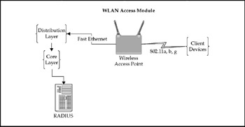
Figure 6-4: Typical WLAN access module
WAN Access Module, Branch Office: Dedicated Media
A typical remote branch office WAN access module consists of standard Layer 2 Ethernet switches and an access router (see Figure 6-5). These offices are usually connected to the data center by dedicated media (frame relay, ISDN, ATM, T1, or similar media) and do not require extensive security such as firewalls. Security is usually in the form of access list filters to control either traffic flow or route distribution (or both). WAN access routers may support Layer 3 QoS if warranted by corporate applications. Where connecting bandwidth is limited, bandwidth managers such as Packeteer PacketShapers may also be included as an optional component.
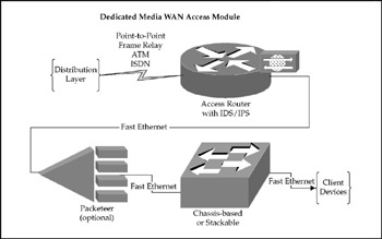
Figure 6-5: Typical branch office WAN access module (dedicated media)
WAN Access Module, Branch Office: VPN Access
Remote offices, which use an office-to-office VPN to tunnel from the branch network to the core network, require compatible VPN hardware at the branch and at the data center. The branch office configuration is similar to the dedicated media branch office with a firewall/VPN device added between the LAN switch and the WAN media (see Figures 6-6 through 6-8). This may be in the form of a VPN/firewall feature incorporated into the WAN access router, or a separate device in line between the switch and the router. In either case, all traffic from the remote site to the data center is encrypted and transported through the VPN tunnel. Internet connectivity may be via any media subject to bandwidth requirements. One key consideration is the added overhead that VPN connectivity requires. IPsec encapsulation adds 1025 percent additional overhead to the data stream, as well as an additional processing workload on the VPN device. When designing VPN connectivity, ensure Internet bandwidth allows for concurrent thin-client sessions plus IPsec overhead.
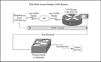
Figure 6-6: Typical branch office WAN access module (VPN router)
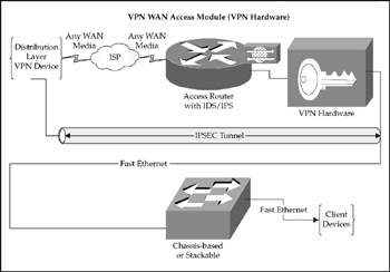
Figure 6-7: Typical branch office WAN Access Module (VPN hardware).
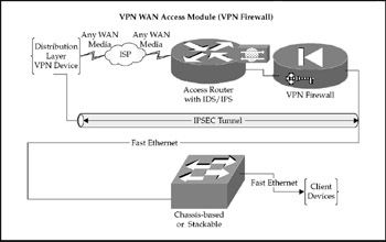
Figure 6-8: Typical branch office WAN access module (VPN firewall)
WAN Access Module, Data Center VPN Termination
When either remote user VPN access or remote office VPN access is required, a VPN termination suite is required at the data center end. If only office-to-office connections and a limited number of user connections are to be supported, corporate firewalls or VPN routers can terminate all required connections. If the capability to terminate connections from multiple branch offices with substantially different VPN needs and/or a large number of users with differing VPN access constraints is needed, consider a purpose-built VPN concentrator. Depending on security requirements, the VPN connections may be routed directly to the corporate LAN or they may be forced through the corporate firewall to apply additional security restrictions.
Data center Internet bandwidth must meet the same capacity requirements as remote branches and may require a separate Internet connection to support VPN terminations (and insulate the VPN Internet connection from the variable bandwidth demands of users surfing the Internet). Optionally, a bandwidth manager (PacketShaper) at the data center access layer can give preferential treatment to IPsec traffic.
Offices that use an office-to-office VPN to tunnel from the branch network to the core network require compatible VPN hardware at the branch and at the data center. The branch office configuration is similar to the dedicated media branch office with a firewall/ VPN device added between the LAN switch and the WAN media (see Figure 6-9). This may be in the form of a VPN/firewall feature incorporated into the WAN access router, or a separate device in line between the switch and the router. In either case, all traffic from the remote site to the data center is encrypted and transported through the VPN tunnel. Internet connectivity may be via any media subject to bandwidth requirements.
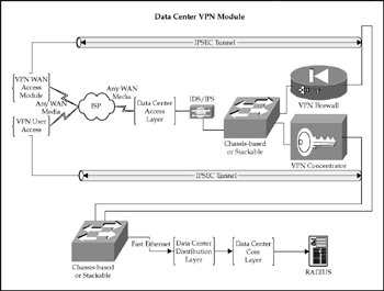
Figure 6-9: Typical data center VPN termination module
WAN Access Module, Remote User Internet Access
The infrastructure suite needed to provide individual remote users with thin-client applications over the Internet exists only at the data center (see Figure 6-10). Actual components of this module are dependent upon the criticality of the remote user access, data security requirements, and the number of remote users. Assuming high-level requirements for all three elements, the module would consist of a redundant Internet upstream connection backed by a redundant firewall. Although Program Neighborhood could be used to enumerate applications, Citrix Web Interface is the preferred method and would require redundancy in DNS servers and front-end Web servers. If secure access is required, redundant Citrix Access Gateway platforms would also be required. Finally, extremely heavy Internet-based user loads, typical of an application service provider, can be augmented with specialized server aggregation appliances such as Citrix's NetScaler to offload DNS and HTTP load balancing.
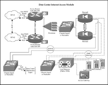
Figure 6-10: Typical data center Internet services access module
Direct Dial Remote Access Module
Dial-up access to the Citrix resources may be either direct asynchronous or PPP-based. Direct access can be to a specific server via multiport modems or modem sharing, but this approach severely limits the ability to effectively balance the client load across the server farm and constrains bandwidth to the client to a maximum of 33.6 Kbps. The preferred solution requires a Remote Access Service (RAS) server or concentrator through either a server platform (Windows Routing and Remote Access) or a concentrator such as a Cisco Universal Gateway or a Lucent Portmaster (see Figure 6-11). In either case, ISDN access, either BRI or PRI, is essential as it allows the RAS device to provide the digital termination of analog or digital calls and achieve speeds greater than 33.6 Kbps. RAS devices require the same type of core services (AAA services) as WLAN modules. In general, a single suite of AAA servers should be able to support WLAN, RAS, and VPN user authentication. As an added benefit, the same RAS device that terminates client connections can also terminate routed ISDN branch-to-branch connections to connect small or home offices to the corporate data center. Accessibility of the data center network from the public switched telephone network (PSTN) mandates strong authentication. Further, firewall filtering of these dial-up connections is highly recommended.
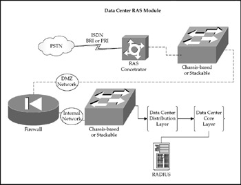
Figure 6-11: Typical data center RAS module
EAN: 2147483647
Pages: 137