Switch Configuration
| < Day Day Up > |
| A high-level overview of the switch configuration is shown in FIGURE 7-18. Figure 7-18. Collapsed Design Without Layer 2 Switches Configuring the Extreme Networks SwitchesFor the multi-tier data center, two Extreme Networks BlackDiamond switches were used for the core switches and one Summit7i switch was used for the edge switch. Note Network equipment from Foundry Networks can be used instead. See "Configuring the Foundry Networks Switches" on page 324. To Configure the Extreme Networks Switches
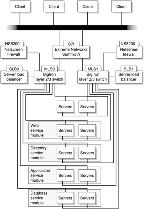
Configuring the Foundry Networks SwitchesThis section describes the network architecture implementation using Foundry Networks equipment instead of Extreme Networks equipment. The overall setup is shown in FIGURE 7-19. Figure 7-19. Foundry Networks Implementation
Master Core Switch ConfigurationCODE EXAMPLE 7-1 shows an example of the configuration file for the master core switch (called MLS0 in the lab). We used the Foundry Networks BigIron switch. Code example 7-1. MLS0 Configuration Filemodule 1 bi-jc-8-port-gig-m4-management-module module 3 bi-jc-48e-port-100-module ! global-protocol-vlan ! vlan 1 name DEFAULT-VLAN by port vlan 10 name refarch by port untagged ethe 1/1 ethe 3/1 to 3/16 router-interface ve 10 vlan 99 name mgmt by port untagged ethe 3/47 to 3/48 router-interface ve 99 ! hostname MLS0 ip default-network 129.146.138.0/16 ip route 192.168.0.0 255.255.255.0 172.0.0.1 ip route 129.148.181.0 255.255.255.0 129.146.138.1 ip route 0.0.0.0 0.0.0.0 129.146.138.1 ! router vrrp-extended interface ve 10 ip address 20.20.0.102 255.255.255.0 ip address 172.0.0.70 255.255.255.0 ip vrrp-extended vrid 1 backup priority 100 track-priority 20 advertise backup ip-address 172.0.0.10 dead-interval 1 track-port e 3/1 enable ip vrrp-extended vrid 2 backup priority 100 track-priority 20 advertise backup ip-address 20.20.0.100 dead-interval 1 track-port e 3/13 enable ! interface ve 99 ip address 129.146.138.10 255.255.255.0 end Standby Core Switch ConfigurationCODE EXAMPLE 7-2 shows a partial listing of the configuration file for the standby core switch (called MLS1 in the lab). Again we used the Foundry Networks BigIron switch. Code example 7-2. MLS1 Configuration Filever 07.5.05cT53 ! module 1 bi-jc-8-port-gig-m4-management-module module 3 bi-jc-48e-port-100-module ! global-protocol-vlan ! vlan 1 name DEFAULT-VLAN by port ! vlan 99 name swan by port untagged ethe 1/6 to 1/8 router-interface ve 99 ! vlan 10 name refarch by port untagged ethe 3/1 to 3/16 router-interface ve 10 ! ! hostname MLS1 ip default-network 129.146.138.0/1 ip route 192.168.0.0 255.255.255.0 172.0.0.1 ip route 0.0.0.0 0.0.0.0 129.146.138.1 ! router vrrp-extended interface ve 10 ip address 20.20.0.102 255.255.255.0 ip address 172.0.0.71 255.255.255.0 ip vrrp-extended vrid 1 backup priority 100 track-priority 20 advertise backup ip-address 172.0.0.10 dead-interval 1 track-port e 3/1 enable ip vrrp-extended vrid 2 backup priority 100 track-priority 20 advertise backup ip-address 20.20.0.100 dead-interval 1 track-port e 3/13 enable interface ve 99 ip address 129.146.138.11 255.255.255.0 ! ! ! ! ! sflow sample 512 sflow source ethernet 3/1 sflow enable ! ! end Server Load BalancerThe following code box shows a partial listing of the configuration file used for the server load balancer (called SLB0 in the lab). We used the Foundry Networks Server XL. Code example 7-3. SLB0 Configuration Filever 07.3.05T12 global-protocol-vlan ! ! server source-ip 20.20.0.50 255.255.255.0 172.0.0.10 ! !! ! server real web1 10.20.0.1 port http port http url "HEAD /" ! server real web2 10.20.0.2 port http port http url "HEAD /" ! ! server virtual WebVip1 192.168.0.100 port http port http dsr bind http web1 http web2 http ! ! vlan 1 name DEFAULT-VLAN by port ver 07.3.05T12 no spanning-tree ! hostname SLB0 ip address 192.168.0.111 255.255.255.0 ip default-gateway 192.168.0.10 web-management allow-no-password banner motd ^C Reference Architecture -- Enterprise Engineering^C Server Load Balancer-- SLB0 129.146.138.12/24^C !! end Server Load BalancerThe following code box shows a partial listing of the configuration file used for the standby server load balancer (called SLB1 in the lab). Again we used the Foundry Networks Server XL. Code example 7-4. SLB1 Configuration Filever 07.3.05T12 global-protocol-vlan ! ! server source-ip 20.20.0.51 255.255.255.0 172.0.0.10 ! !! ! server real s1 20.20.0.1 port http port http url "HEAD /" ! server real s2 20.20.0.2 port http port http url "HEAD /" ! ! server virtual vip1 172.0.0.11 port http port http dsr bind http s1 http s2 http ! ! vlan 1 name DEFAULT-VLAN by port ver 07 .3.05T12 ! hostname SLB1 ip address 172.0.0.112 255.255.255.0 ip default-gateway 172.0.0.10 web-management allow-no-password banner motd ^C Reference Architecture - Enterprise Engineering^C Server Load Balancer - SLB1 - 129.146.138.13/24^C ! |
| < Day Day Up > |
EAN: 2147483647
Pages: 116