QoS Components
| < Day Day Up > |
| To give you enough background on the fundamentals and an implementation perspective, this section describes the overall network and systems architecture and identifies the sources of delays. It also explains why QoS is essentially about controlling network and system resources in order to achieve more predictable delays for preferred applications. Implementation FunctionsThree necessary implementation functions are:
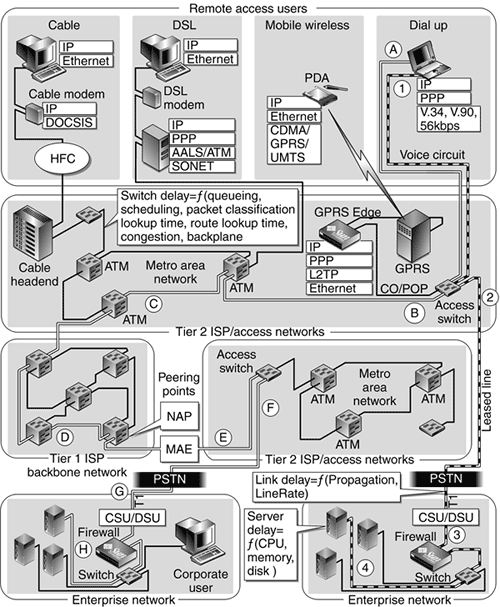
QoS MetricsQoS is defined by a multitude of metrics. The simplest is bandwidth, which can be conceptually viewed as a logical pipe of a larger pipe. However, actual network traffic is bursty, so a fixed bandwidth would be wasteful because at one instant in time one flow might use 1 percent of this pipe while another might need 110 percent of the allocated pipe. To reduce waste, certain burst metrics are used to determine how much of a burst and how long a burst can be tolerated. Other important metrics that directly impact the quality of service include packet loss rate, delay, and jitter (variation in delay). The network and computing components that control these metrics are described later in this chapter. Network and Systems Architecture OverviewTo fully understand where QoS fits into the overall picture of network resources, it is useful to take a look at the details of the complete network path traversal, starting from the point where a client sends a request, traverses various network devices, and finally arrives at the destination where the server processes the request. Different classes of applications have different characteristics and requirements (see the "The Need for QoS" on page 91 for additional details). Because several federated networks with different traffic characteristics are combined, end-to-end QoS is a complex issue. FIGURE 4-10 illustrates a high-level overview of the components involved in an end-to-end packet traversal for an enterprise that relies on a service provider. Two different paths are shown. Both originate from the client and end at a server. Figure 4-10. Overview of End-to-End Network and Systems Architecture Path A-H is a typical scenario, where the client and server are connected to different local ISPs and must traverse different ISP networks. Multiple Tier 1 ISPs can be traversed, connected together by peering points such as MAE-East or private peering points such as Sprint's NAP. Path 1-4 shows an example of the client and server connected to the same local Tier 2 ISP, when both client and server are physically located in the same geographical area. In either case, the majority of the delays are attributed to the switches. In the Tier 2 ISPs, the links from the end-user customers to the Tier 2 ISP tend to be slow links, but the Tier 2 ISP aggregates many links, hoping that not all subscribers will use the links at the same time. If they do, packets get buffered up and eventually are dropped. Implementing QoSYou can implement QoS in many different ways. Each domain has control over its resources and can implement QoS on its portion of the end-to-end path using different technologies. Two domains of implementation are enterprises and network service providers.
ATM QoS ServicesIt is interesting that NSPs implement QoS at both the IP layer and the asynchronous transfer mode (ATM) layer. Most ISPs still have ATM networks that carry IP traffic. ATM itself offers six types of QoS services:
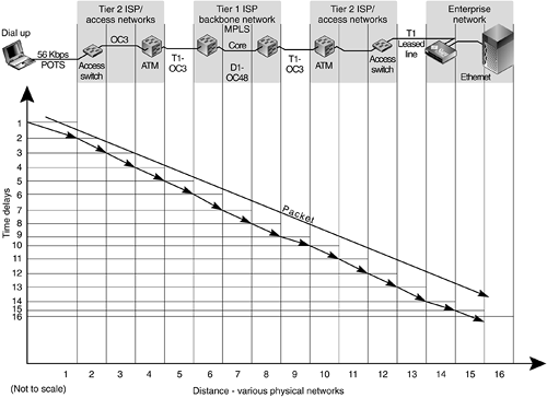
One of the main difficulties in providing an end-to-end QoS solution is that so many private networks must be traversed, and each network has its own QoS implementations and business objectives. The Internet is constructed so that networks interconnect or "peer" with other networks. One network might need to forward traffic of other networks. Depending on the arrangements, competitors might not forward the traffic in the most optimal manner. This is what is meant by business objectives. Sources of Unpredictable DelayFrom a system computing perspective, unpredictable delays are often due to limited CPU resources or disk I/O latencies. These degrade during a heavy load. From a network perspective, many components add up to the cumulative end-to-end delay. This section describes some of the important components that contribute to delay and explains the choke points at the access networks, where the traffic is aggregated and forwarded to a backbone or core. Service providers overallocate their networks to increase profits and hope that not all subscribers will access the network at the same time. FIGURE 4-11 was constructed by taking out path A-G in FIGURE 4-10 and projecting it onto a Time-Distance plane. This is a typical Web client accessing the Internet site of an enterprise. The vertical axis indicates the time that elapsed for a packet to travel a certain link segment. The horizontal axis indicates the link segment that the packet traverses. At the top, we see the network devices and vertical lines that project down to the distance axis, showing the corresponding link segment. In this illustration, an IP packet's journey starts when a user clicks on a Web page. The HTTP request maps first to a TCP three-way handshake to create a socket connection. The first TCP packet is the initial SYN packet, which first traverses segment 1 and is usually quite slow because this link is typically 30 kbit/sec over a 56 kbit/sec modem, depending on the quality and distance of the "last mile" wiring. Figure 4-11. One-Way End-to-End Packet Data Path Transversal Network Delay is composed of the following components:
The odd-numbered links of FIGURE 4-11 represent the link delays. Note that segment and link are used interchangeably.
The even-numbered links of FIGURE 4-11 represent the delays experienced in switches. These delays are composed of switching delays, route lookups, packet classification, queueing, packet scheduling, and internal switch forwarding delays, such as sending a packet from the ingress unit through the backplane to the egress unit. As FIGURE 4-11 illustrates, QoS is needed to control access to shared resources during episodes of congestion. The shared resources are servers and specific links. For example, Link 1 is a dedicated point-to-point link, where a dedicated voice channel is set up at call time with a fixed bandwidth and delay. Link 13 is a permanent circuit as opposed to a switched dedicated circuit. However, this is a digital line. QoS is usually implemented in front of a congestion point. QoS restricts the traffic that is injected into the congestion point. Enterprises have QoS functions that restrict the traffic being injected into their service provider. The ISP has QoS functions that restrict the traffic injected into their core. Tier 2 ISPs oversubscribe their bandwidth capacities, hoping that not all their customers will need bandwidth at the same time. During episodes of congestion, switches buffer packets until they can be transmitted. Links 5 and 9 are boundary links that connect two untrusted parties. The Tier 2 ISP must control the traffic injected into the network that must be handled by the Tier 1 ISP's core network. Tier 1 polices the traffic that customers inject into the network at Links 5 and 9. At the enterprise, many clients need to access the servers. |
| < Day Day Up > |
EAN: 2147483647
Pages: 116