Looking Back at Traditional CampusNetworks
Looking Back at Traditional Campus Networks
In the 1990s, the traditional campus network started as one LAN and grew and grew until segmentation needed to take place just to keep the network up and running. In this era of rapid expansion, response time was secondary to just making sure the network was functioning. Besides, the majority of applications were store-and-forward, such as e-mail, and there was little need for advanced quality of service options.
By looking at the technology, you can see why keeping the network running was such a challenge. Typical campus networks ran on 10BaseT or 10Base2 (thinnet). As a result, the network was one large collision domain—not to mention even one large broadcast domain. Despite these limitations, Ethernet was used because it was scalable, effective, and somewhat inexpensive compared to other options. (IBM “owned” Token Ring, and getting it installed frequently meant getting in IBM to do it—sometimes expensive and often impractical.) ARCnet was used in some networks, but Ethernet and ARCnet are not compatible, and the networks became two separate entities. ARCnet soon became history. Token Ring became marginalized. Ethernet became king.
Because a campus network can easily span many buildings, bridges were used to connect the buildings; this broke up the collision domains, but the network was still one large broadcast domain. More and more users were attached to the hubs used in the network, and soon the performance of the network was considered extremely slow.
Performance Problems and Solutions
Availability and performance are the major problems with traditional campus networks. Availability is affected by the number of users attempting to access the network at any one time, plus the reliability of the network itself. The performance problems in traditional campus networks include collisions, bandwidth, broadcasts, and multicasts.
Collisions
A campus network typically started as one large collision domain, so all devices could see and also collide with each other. If a host had to broadcast, then all other devices had to listen, even though they themselves were trying to transmit. And if a device were to exhibit a jabber (malfunction by continually transmitting), it could bring down the entire network.
Because routers didn’t really become cost effective until the late 1980s, bridges were used to break up collision domains. That created smaller collision domains, and was therefore an improvement, but the network was still one large broadcast domain and the same old broadcast problems still existed. Bridges also solved distance-limitation problems because they usually had repeater functions built into the electronics and/or they could break up the physical segment.
Bandwidth
The bandwidth of a segment is measured by the amount of data that can be transmitted at any given time. Think of bandwidth as a water hose; the amount of water that can go through the hose depends on two elements:
-
Pressure
-
Distance
The pressure is the current, and the bandwidth is the size of the hose. If you have a hose that is only 1/4-inch in diameter, you won’t get much water through it regardless of the current or the size of the pump on the transmitting end.
Another issue is distance. The longer the hose, the more the water pressure drops. You can put a repeater in the middle of the hose and re-amplify the pressure of the line, which would help, but you need to understand that all lines (and hoses) have degradation of the signal, which means that the pressure drops off the further the signal goes down the line. For the remote end to understand digital signaling, the pressure must stay at a minimum value. If it drops below this minimum value, the remote end will not be able to receive the data. In other words, the far end of the hose would just drip water instead of flow. You can’t water your crops with drips of water; you need a constant water flow.
The solution to bandwidth issues is maintaining your distance limitations and designing your network with proper segmentation of switches and routers. Congestion on a segment happens when too many devices are trying to use the same bandwidth. By properly segmenting the network, you can eliminate some of the bandwidth issues. You never will have enough bandwidth for your users; you’ll just have to accept that fact. However, you can always make it better.
Broadcasts and Multicasts
Remember that all protocols have broadcasts built in as a feature, but some protocols can really cause problems if not configured correctly. Some protocols that, by default, can cause problems if they are not correctly implemented are Internet Protocol (IP), Address Resolution Protocol (ARP), Network Basic Input Output System (NetBIOS), Internetwork Packet Exchange (IPX), Service Advertising Protocol (SAP), and Routing Information Protocol (RIP). However, remember that there are features built into the Cisco router Internetworking Operating System (IOS) that, if correctly designed and implemented, can alleviate these problems. Packet filtering, queuing, and choosing the correct routing protocols are some examples of how Cisco routers can eliminate some broadcast problems.
Multicast traffic can also cause problems if not configured correctly. Multicasts are broadcasts that are destined for a specific or defined group of users. If you have large multicast groups or a bandwidth-intensive application such as Cisco’s IPTV application, multicast traffic can consume most of the network bandwidth and resources.
To solve broadcast issues, create network segmentation with bridges, routers, and switches. However, understand that you’ll move the bottleneck to the routers, which break up the broadcast domains. Routers process each packet that is transmitted on the network, which can cause a bottleneck if an enormous amount of traffic is generated.
Just in case anyone is still confused about broadcasts, consider this analogy. Suppose you worked in an office where there was a telephone system that included a broadcast capability. Every time the phone rang, everyone would have to answer it and listen to who the broadcast transmission was aimed at—“Hello, is that the Domain Name Server?” How long would it be before all these interruptions caused you to throw the phone out of the window? That’s what broadcasts do to PCs. Each interruption causes single-tasking operating systems to stop what they are doing—writing to the hard drive, processing, and so on—and answer the phone.
Virtual LANs (VLANs) are a solution as well, but VLANs are just broadcast domains with artificial boundaries. A VLAN is a group of devices on different network segments defined as a broadcast domain by the network administrator. The benefit of VLANs is that physical location is no longer a factor for determining the port into which you would plug a device into the network. You can plug a device into any switch port, and the network administrator gives that port a VLAN assignment. Remember that routers or layer 3 switches must be used for different VLANs to communicate.
The 80/20 Rule
The traditional campus network placed users and groups in the same physical location. If a new salesperson was hired, they had to sit in the same physical location as the other sales personnel and be connected to the same physical network segment in order to share network resources. Any deviation from this caused major headaches for the network administrators.
The rule that needed to be followed in this type of network was called the 80/20 rule because 80 percent of the users’ traffic was supposed to remain on the local network segment and only 20 percent or less was supposed to cross the routers or bridges to the other network segments. If more than 20 percent of the traffic crossed the network segmentation devices, performance issues arose. Figure 1.1 shows a traditional 80/20 network.
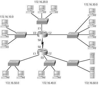
Figure 1.1: A traditional 80/20 network
Because network administrators are responsible for network design and implementation, they improved network performance in the 80/20 network by making sure that all the network resources for the users were contained within the local network segment. The resources included network servers, printers, shared directories, software programs, and applications.
The New 20/80 Rule
With new web-based applications and computing, any PC can be a subscriber or publisher at any time. Also, because businesses are pulling servers from remote locations and creating server farms (sounds like a mainframe, doesn’t it?) to centralize network services for security, reduced cost, and administration, the old 80/20 rule is obsolete and could not possibly work in this environment. All traffic must now traverse the campus backbone, which means we now have a 20/ 80 rule in effect. Twenty percent of what the user performs on the network is local, whereas up to 80 percent crosses the network segmentation points to get to network services. Figure 1.2 shows the new 20/80 network.
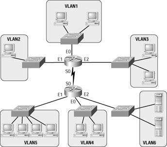
Figure 1.2: A 20/80 network
The problem with the 20/80 rule is not the network wiring and topology as much as it is the routers themselves. They must be able to handle an enormous number of packets quickly and efficiently at wire speed. This is probably where I should be talking about how great Cisco routers are and how our networks would be nothing without them. I’ll get to that later in this chapter—trust me.
Virtual LANs
With this new 20/80 rule, more and more users need to cross broadcast domains (VLANs), and this puts the burden on routing, or layer 3 switching. By using VLANs within the new campus model, you can control traffic patterns and control user access easier than in the traditional campus network. Virtual LANs break up broadcast domains by using either a router or a switch that can perform layer 3 functions. Figure 1.3 shows how VLANs are created and might look in an internetwork.
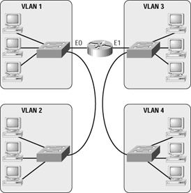
Figure 1.3: VLANs break up broadcast domains in a switched internetwork.
Chapter 3, “VLANs, Trunks, and VTP,” includes detailed information about VLANs and how to configure them in an internetwork. It is imperative that you understand VLANs, because the traditional way of building the campus network is being redesigned and VLANs are a large factor in building the new campus model.
EAN: 2147483647
Pages: 174