12.5 System Buses and Data Transfer Rates
12.5 System Buses and Data Transfer Rates
Earlier in this book, you saw that the CPU communicates with memory and I/O devices using the system bus. If you've ever opened up a computer and looked inside or read the specifications for a system, you've probably seen terms like PCI, ISA, EISA , or even NuBus mentioned when discussing the computer's system bus. In this section, we'll discuss the relationship between the CPU's bus and these different system buses, and describe how these different computer system buses affect the performance of a system.
Although the choice of the hardware bus is made by hardware engineers, not software engineers , many computer systems will actually employ multiple buses in the same system. Therefore, software engineers can choose which peripheral devices they use based upon the bus connections of those peripherals. Furthermore, maximizing performance for a particular bus may require different programming techniques than for other buses. Finally, although a software engineer may not be able to choose the buses available in a particular computer system, that engineer can choose which system to write their software for, based on the buses available in the system they ultimately choose.
Computer system buses like PCI (Peripheral Component Interconnect) and ISA (Industry Standard Architecture) are definitions for physical connectors inside a computer system. These definitions describe the set of signals, physical dimensions (i.e., connector layouts and distances from one another), and a data transfer protocol for connecting different electronic devices. These buses are related to the CPU's local bus , which consists of the address, data, and control lines, because many of the signals on the peripheral buses are identical to signals that appear on the CPU's bus.
However, peripheral buses do not necessarily mirror the CPU's bus - they often contain several lines that are not present on the CPU's bus. These additional lines let peripheral devices communicate with one another without having to go through the CPU or memory. For example, most peripheral buses provide a common set of interrupt control signals that let I/O devices communicate directly with the system's interrupt controller, which is also a peripheral device. Nor do the peripheral buses include all the signals found on the CPU's bus. For example, the ISA bus only supports 24 address lines compared with the Pentium IV's 36 address lines.
Different peripheral devices are designed to use different peripheral buses. Figure 12-6 shows the organization of the PCI and ISA buses in a typical computer system.
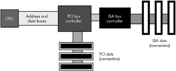
Figure 12-6: Connection of the PCI and ISA buses in a typical PC
Notice how the CPU's address and data buses connect to a PCI bus controller peripheral device, but not to the PCI bus itself. The PCI bus controller contains two sets of pins, providing a bridge between the CPU's local bus and the PCI bus. The signal lines on the local bus are not connected directly to the corresponding lines on the PCI bus; instead, the PCI bus controller acts as an intermediary, rerouting all data transfer requests between the CPU and the PCI bus.
Another interesting thing to note is that the ISA bus controller is not directly connected to the CPU. Instead, it is usually connected to the PCI bus controller. There is no logical reason why the ISA controller couldn't be connected directly to the CPU's local bus. However, in most modern PCs, the ISA and PCI controllers appear on the same chip, and the manufacturer of this chip has chosen to interface the ISA bus through the PCI controller for cost or performance reasons.
The CPU's local bus usually runs at some submultiple of the CPU's frequency. Typical local bus frequencies are currently 66 MHz, 100 MHz, 133 MHz, 400 MHz, 533 MHz, and 800 MHz, but they may become even faster. Usually, only memory and a few selected peripherals like the PCI bus controller sit on the CPU's bus and operate at this high frequency.
Because a typical CPU's bus is 64 bits wide and because it is theoretically possible to achieve one data transfer per clock cycle, the CPU's bus has a maximum possible data transfer rate of eight bytes times the clock frequency, or 800 MB per second for a 100-MHz bus. In practice, CPUs rarely achieve the maximum data transfer rate, but they do achieve some percentage of it, so the faster the bus, the more data can move in and out of the CPU (and caches) in a given amount of time.
12.5.1 Performance of the PCI Bus
The PCI bus comes in several configurations. The base configuration has a 32-bit-wide data bus operating at 33 MHz. Like the CPU's local bus, the PCI bus is theoretically capable of transferring data on each clock cycle. This means that the bus has a theoretical maximum data transfer rate of 4 bytes times 33 MHz, or 132 MB per second. In practice, though, the PCI bus doesn't come anywhere near this level of performance except in short bursts.
Whenever the CPU wishes to access a peripheral on the PCI bus, it must negotiate with other peripheral devices for the right to use the bus. This negotiation can take several clock cycles before the PCI controller grants the CPU access to the bus. If a CPU writes a sequence of values to a peripheral device at a rate of a double word per bus transfer, you can see that the negotiation time actually causes the transfer rate to drop dramatically. The only way to achieve anywhere near the maximum theoretical bandwidth on the bus is to use a DMA controller and move blocks of data in burst mode . In this burst mode, the DMA controller negotiates just once for the bus and then makes a large number of transfers without giving up the bus between each one.
There are a couple of enhancements to the PCI bus that improve performance. Some PCI buses support a 64-bit wide data path . This, obviously, doubles the maximum theoretical data transfer rate from four bytes per transfer to eight bytes per transfer. Another enhancement is running the bus at 66 MHz, which also doubles the throughput. With a 64-bit-wide 66-MHz bus you would quadruple the data transfer rate over the performance of the baseline configuration. These optional enhancements to the PCI bus allow it to grow with the CPU as CPUs increase their performance. As this is being written, a high-performance version of the PCI bus, PCI-X, is starting to appear with expected bus speeds beginning at 133 MHz and other enhancements to improve performance.
12.5.2 Performance of the ISA Bus
The ISA bus is a carry-over from the original PC/AT computer system. This bus is 16 bits wide and operates at 8 MHz. It requires four clock cycles for each bus cycle. For this and other reasons, the ISA bus is capable of about only one data transmission per microsecond. With a 16-bit-wide bus, data transfer is limited to about 2 MB per second. This is much slower than the speed at which both the CPU's local bus and the PCI bus operate. Generally, you would only attach low-speed devices, like an RS-232 communications device, a modem, or a parallel printer interface, to the ISA bus. Most other devices, like disks, scanners , and network cards, are too fast for the ISA bus. The ISA bus is really only capable of supporting low-speed and medium-speed devices.
Note that accessing the ISA bus on most systems involves first negotiating for the PCI bus. The PCI bus is so much faster than the ISA bus that the negotiation time has very little impact on the performance of peripherals on the ISA bus. Therefore, there is very little difference to be gained by connecting the ISA controller directly to the CPU's local bus.
12.5.3 The AGP Bus
Video display cards are very special peripherals that need maximum bus performance to ensure quick screen updates and fast graphic operations. Unfortunately, if the CPU has to constantly negotiate with other peripherals for the use of the PCI bus, graphics performance can suffer. To overcome this problem, video card designers created the AGP (Accelerated Graphics Port) interface between the CPU's local bus and the video display card, which provides various control lines and bus protocols specifically designed for video display cards.
The AGP connection lets the CPU quickly move data to and from the video display RAM (see Figure 12-7). Because there is only one AGP port per system, only one card can use the AGP slot at a time. The upside of this is that the system never has to negotiate for access to the AGP bus.
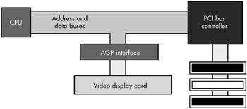
Figure 12-7: The AGP bus interface
EAN: 2147483647
Pages: 144