Installing, Configuring, and Troubleshooting Network Protocols
Installing, Configuring, and Troubleshooting Network ProtocolsWindows 2000 supports a variety of network protocols, the most popular of which is the Transmission Control Protocol/Internet Protocol ( TCP / IP ) . The different protocols enable a Windows 2000 Server to interoperate in a number of network environments, and to support multiple client platforms, as well as different services and applications. Because network communication is dependent on network protocols, it's important to have the knowledge necessary to install, configure, and troubleshoot them. The following sections cover the fundamentals regarding the two main network protocols supported by Windows 2000: TCP/IP and NWLink. Installing and Configuring TCP/IPTCP/IP is an industry standard suite of protocols and utilities that enables communication between hosts on a network. Because of the increasing popularity of TCP/IP, it is quickly becoming the protocol of choice in many network environments. You will find that most operating systems today, including Windows 2000, provide support for TCP/IP. How a suite of protocols performs is described through the Open Systems Interconnection (OSI) Model. The OSI Model consists of seven layers . The protocols within a protocol suite, such as TCP/IP, operate at different layers of the model, performing different functions to enable network communication. The seven layers of the OSI model are as follows :
The suite of protocols that make up TCP/IP also map to a model referred to as the Department of Defense (DoD) model. This model defines communication in four layers. Each of the four layers maps to the different layers within the OSI model and each layer of the model also defines a specific role or function. The different protocols making up the suite each function at a specific layer and work together to provide network communication. The four layers of the DoD model include:
IP AddressingFor packets to be routed on an IP network, every host requires a unique IP address (hosts can include workstations, servers, routers, printers, or any other device with a network interface card). The IP address is a 32-bit number, represented in decimal format, that identifies each host. An IP address consists of two parts : the network ID and the host ID . The network ID is used to identify a specific network or subnet, whereas the host ID identifies the hosts on a given network or subnet. For example, an IP address of 132.10.26.2 has a network ID of 132.10 and a host ID of 26.2 .
IP addresses are organized into different address classes that define the number of bits out of the 32 that are used to identify the network. These classes also identify the number of bits used to identify the hosts on a network. By examining the address classes, you can also determine the number of networks and the number of hosts. Table 5.1 summarizes the different address classes. Table 5.1. TCP/IP Address Classes
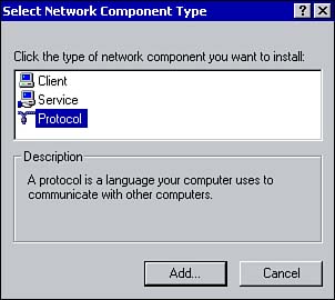
Table 5.1 summarizes three of the address classes. There are also Classes D and E. Class D is reserved for multicasting and Class E is reserved for testing purposes, but neither of these is relevant to Windows networking. You can determine the class of an IP address by mapping the first decimal value (the number before the first period) to one of the ranges outlined in Table 5.1. For example, 198.221.10.254 is a Class C address. When assigning IP addresses, each host also requires a subnet mask , which determines which part of an IP address is used as the network ID and which is used to identify a host. For example, the default subnet mask for a Class C address is 255.255.255.0 , which means the first three decimal places (called octets) identify the network and the last octet identifies the host. The subnet mask is also used to determine whether the destination host is on the local or a remote subnet. The subnet mask of the local host is compared against the IP address of the destination host and, through a process known as "anding," it is determined whether the destination IP address is local or remote. (This is called an adjacency test .) Installing TCP/IPDuring the installation of Windows 2000, TCP/IP is automatically installed by default when a network adapter is detected , unless you override the default settings. If it wasn't installed during setup or if you need to add it again, you can do so through the Network and Dial-up Connections applet within the Control Panel. The following steps will help you install TCP/IP:
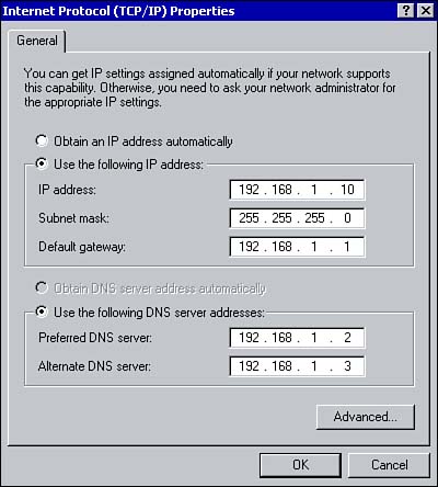
Configuring TCP/IPAs discussed in Chapter 2, "DNS," IP addresses can be assigned dynamically or statically. When TCP/IP is installed, it is automatically configured to use the Dynamic Host Configuration Protocol (DHCP). If you choose the have an IP address assigned dynamically, you can leave the default configuration as is.
However, for many servers, depending on the role configured, it is recommended or even required that you statically configure an IP address. For example, if you install Active Directory on a server with a dynamically assigned IP address, a warning will appear during the installation informing you that the server should be configured with a static IP address. Or if you are installing the DHCP service, the server must first be configured with a static IP address. TCP/IP can be configured using the Properties window for the Local Area Connection by performing the following steps:
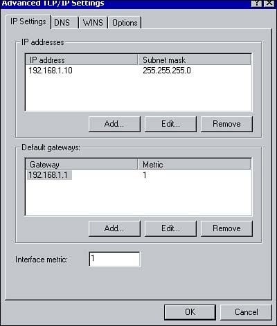
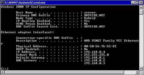
You can configure advanced settings by clicking the Advanced button shown in Figure 5.2. The Advanced TCP/IP Settings window appears, as shown in Figure 5.3. Using the TCP/IP Settings tab, you can assign additional IP addresses to the network connection. For example, a single connection can be assigned a private address for the internal network and a public address for the Internet. The Interface metric box allows you to associate a cost with the route. Figure 5.3. Configuring advanced TCP/IP settings. Testing TCP/IPOnce the necessary settings have been specified, the configuration can be tested using the ipconfig and ping commands. Using ipconfig , you can verify the settings that have been configured. To do so, open the Command Prompt window and type ipconfig (using the /all parameter brings up more detailed configuration information), as shown in Figure 5.4. Table 5.2 outlines some of the common parameters that can be used with the ipconfig command. Figure 5.4. Verifying TCP/IP configuration using the ipconfig command. Table 5.2. Parameters Used with the ipconfig Command
Use the ping command to verify connectivity with other hosts on a TCP/IP network. Connectivity on the network is verified by sending Internet Control Message Protocol (ICMP) echo requests and replies. When the ping command is issued, the source computer sends echo requests messages to another TCP/IP host. The remote host, if reachable , then responds with four echo replies. The ping command is also issued at the command prompt along with the TCP/IP address or domain name of the other TCP/IP host, as follows: C:> ping 124.120.105.110 or C:> ping www.bayside.net
The general steps for troubleshooting TCP/IP using the ping command are as follows:
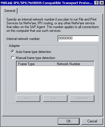
Two other utilities that you can use for TCP/IP troubleshooting are tracert and pathping . The tracert command determines the route that is taken to a specific destination. You may want to use the tracert command if you are not able to successfully ping the IP address of a remote host. The results of the tracert command indicate if there is a problem with a router or gateway between the local computer and the remote destination. The pathping command is basically a combination of the ping and tracert commands. When the command is issued, packets are sent to each router between the local computer and a remote computer. The results determine which routers and gateways may be causing problems on the network. Installing the NWLink ProtocolIf there are NetWare servers hosting resources on the network, you'll want to install the NWLink protocol. This is Microsoft's 32-bit version of Novell's Internetwork Packet Exchange/Sequences Packet Exchange (IPX/SPX) protocol used to communicate with NetWare servers. NWLink is not installed by default like TCP/IP, but can be installed using the same steps outlined in the section on installing TCP/IP, only choose to install the NWLink IPX/SPX NetBIOS Compatible Transport Protocol instead. Once it's installed, it can be configured using the Properties window of the local area connection. Configuring NWLinkThere are two configuration settings for the NWLink protocol. The first is the internal network number ; the second is the frame type . From the Properties window of the local area connection, select NWLink IPX/SPX/NetBIOS Compatible Transport Protocol (see Figure 5.5). Figure 5.5. Configuring the NWLink protocol. The internal network number is used for internal routing. By using the internal network number, virtual networks can be created. If there are multiple network adapters, information can be more efficiently routed to the services running on a computer. The default internal network number is automatically set to all zeros. The following list describes certain instances in which the number must be manually configured:
The frame type defines how a computer running Windows 2000 and NWLink formats data being sent on the network ( specifically the header and footer information). To communicate with a NetWare server, the computer running Windows 2000 must be using the same frame type. If there is only one frame type being used on the network, such as 802.2 for example, you can leave the frame type to autodetect. Once NWLink is installed, the frame type will be automatically detected. If there are multiple frame types detected, NWLink will default to 802.2. You may need to configure the frame type if you have more than one NetWare server on the network using different frame types, because the frame types are not compatible. To manually configure the frame type, select Manual Frame Type Detection and click the Add button from the Properties window for NWLink. When configuring the frame types, keep the following points in mind:
Communicating with NetWare ServersInstalling the NWLink protocol does not in itself enable a computer to access a NetWare server; additional software must be installed. Client Service for NetWare ( CSNW ) enables a computer to directly access resources on a NetWare server. Each client requiring access to resources on the NetWare server must have a user account. Gateway Service for NetWare ( GSNW ) enables a Windows 2000 server to act as a gateway for clients when accessing resources on a NetWare server, eliminating the need for clients to be running NetWare client software. Once GSNW is installed on a Windows 2000 server, Microsoft clients can gain access to NetWare resources through the gateway. Installing GSNW reduces administration because the gateway is the only computer that requires a user account on the NetWare server. You don't have to install any additional software on the workstations. The software you choose to install depends on the network environment. If your network consists of both Windows 2000 and NetWare servers, consider installing CSNW on all clients so they can directly access the NetWare servers. If you intend to migrate the NetWare servers to Windows 2000, consider installing GSNW to decrease administration. To install CSNW on a Windows 2000 Professional workstation, perform the following steps:
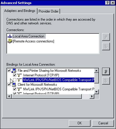
GSNW is installed on a Windows 2000 server using the preceding process. The difference being when you select to Add a new client, you must install Gateway (and Client) Service for NetWare. During the installation of GSNW, NWLink and CSNW are installed and a Gateway Service for NetWare applet is added to the Control Panel. The GSNW applet is used to configure the gateway for NetWare connectivity. If you are working within a Novell NDS environment, specify the default tree and context. This identifies the position of the user object within the NDS tree that the GSNW server logs on with. If you are not in an NDS environment, specify the preferred server. The preferred server is the NetWare server you are automatically connected to when you log on. You must also create a group called NTGATEWAY on the NetWare server. Within the group, a user account must be added. This is the user account the GSNW server uses to access resources on the NetWare server. The final step is to actually enable the gateway. Again, you can do this by using the GSNW applet within the Control Panel. Simply open the applet and click the Gateway button. Select the option to Enable Gateway and type the username and password for the account on the NetWare server. You can then use the Add button to configure the NetWare resources that will be available to clients through the gateway. Configuring Network BindingsMost servers have a number of protocols and services installed as well as multiple network adapters. Bindings determine the protocols and services that are available to a particular network adapter card as well as the order in which they are used. For example, a local network may use TCP/IP as its primary communication protocol but require NWLink for occasional access to a NetWare server. Because the server attempts any network connectivity using the first protocol bound to the network adapter card, the most frequently used protocol should be listed first. Another example is installing WINS but unbinding it from the external interface connected to the Internet for security purposes. Configuring the bindings can also aid in reducing network traffic. If a network rarely uses NWLink except for occasional access to a NetWare server and it is listed first in the binding order, the server will attempt to use this protocol first for any network communication, thereby generating unnecessary network traffic. To configure the bindings for a network connection, perform the following steps:
|
EAN: 2147483647
Pages: 167