Foundation Topics
Router Redundancy in Multilayer SwitchingMultilayer switches can act as IP gateways for connected hosts by providing gateway addresses at VLAN SVIs and Layer 3 physical interfaces. These switches can also participate in routing protocols, just as traditional routers do. For high availability, multilayer switches should offer a means of preventing one switch (gateway) failure from isolating an entire VLAN. This chapter discusses several approaches to providing router redundancy, including the following:
Packet Forwarding ReviewWhen a host must communicate with a device on its local subnet, it can generate an Address Resolution Protocol (ARP) request, wait for the ARP reply, and exchange packets directly. However, if the far end is located on a different subnet, the host must rely on an intermediate system (a router, for example) to relay packets to and from that subnet. A host identifies its nearest router, also known as the default gateway or next hop, by its IP address. If the host understands something about routing, it recognizes that all packets destined off-net must be sent to the gateway's MAC address rather than the far end's MAC address. Therefore, the host first sends an ARP request to find the gateway's MAC address. Then packets can be relayed to the gateway directly without having to look for ARP entries for individual destinations. If the host is not so savvy about routing, it might still generate ARP requests for every off-net destination, hoping that someone will answer. Obviously, the off-net destinations cannot answer because they never receive the ARP request broadcasts; these requests are not forwarded across subnets. Instead, you can configure the gateway to provide a proxy ARP function so that it will reply to ARP requests with its own MAC address, as if the destination itself had responded. Now the issue of gateway availability becomes important. If the gateway router for a subnet or VLAN goes down, packets have no way of being forwarded off the local subnet. Several protocols are available that allow multiple routing devices to share a common gateway address so that if one goes down, another automatically can pick up the active gateway role. The sections that follow describe these protocols. Hot Standby Router ProtocolHSRP is a Cisco-proprietary protocol developed to allow several routers (or multilayer switches) to appear as a single gateway IP address. RFC 2281 describes this protocol in more detail. Basically, each of the routers that provides redundancy for a given gateway address is assigned to a common HSRP group. One router is elected as the primary, or active, HSRP router; another is elected as the standby HSRP router; and all the others remain in the listen HSRP state. The routers exchange HSRP hello messages at regular intervals so they can remain aware of each other's existence and that of the active router. Note HSRP sends its hello messages to the multicast destination 224.0.0.2 ("all routers") using UDP port 1985. An HSRP group can be assigned an arbitrary group number, from 0 to 255. If you configure HSRP groups on several VLAN interfaces, it can be handy to make the group number the same as the VLAN number. However, most Catalyst switches support only up to 16 unique HSRP group numbers. If you have more than 16 VLANs, you will quickly run out of group numbers. An alternative is to make the group number the same (that is, 1) for every VLAN interface. This is perfectly valid because the HSRP groups are only locally significant on an interface. In other words, HSRP Group 1 on interface VLAN 10 is unique and independent from HSRP Group 1 on interface VLAN 11. HSRP Router ElectionHSRP election is based on a priority value (0 to 255) that is configured on each router in the group. By default, the priority is 100. The router with the highest priority value (255 is highest) becomes the active router for the group. If all router priorities are equal or set to the default value, the router with the highest IP address on the HSRP interface becomes the active router. To set the priority, use the following interface-configuration command: Switch(config-if)# standby group priority priorityFor example, suppose that one switch is left at its default priority of 100, while the local switch is intended to win the active role election. You can use the following command to set the HSRP priority to 200: Switch(config-if)# standby 1 priority 200When HSRP is configured on an interface, the router progresses through a series of states before becoming active. This forces a router to listen for others in a group and see where it fits into the pecking order. Devices participating in HSRP must progress their interfaces through the following state sequence:
Only the standby (the one with the second-highest priority) router monitors the hello messages from the active router. By default, hellos are sent every 3 seconds. If hellos are missed for the duration of the holdtime timer (default 10 seconds, or three times the hello timer), the active router is presumed to be down. The standby router is then clear to assume the active role. At that point, if other routers are sitting in the Listen state, the next-highest priority router is allowed to become the new standby router. If you need to change the timer values, use the following interface-configuration command. If you decide to change the timers on a router, you should change them identically on all routers in the HSRP group. Switch(config-if)# standby group timers [msec] hello [msec] holdtimeThe hello and holdtime values can be given in seconds or in milliseconds, if the msec keyword precedes a value. The hello time can range from 1 to 254 seconds or from 15 to 999 milliseconds. The holdtime always should be at least three times the hello timer, and can range from 1 to 255 seconds or 50 to 3000 milliseconds. As an example, the following command can be used to set the hello time at 100 milliseconds and the holdtime to 300 milliseconds: Switch(config-if)# standby 1 timers msec 100 msec 300Note Be aware that decreasing the HSRP hello time allows a router failure to be detected more quickly. At the same time, HSRP hellos will be sent more often, increasing the amount of traffic on the interface. Normally, after the active router fails and the standby becomes active, the original active router cannot immediately become active when it is restored. In other words, if a router is not already active, it cannot become active again until the current active router failseven if its priority is higher than that of the active router. An interesting case arises when routers are just being powered up or added to a network. The first router to bring up its interface becomes the HSRP active router, even if it has the lowest priority of all. You can configure a router to pre-empt or immediately take over the active role if its priority is the highest at any time. Use the following interface-configuration command to allow pre-emption: Switch(config-if)# standby group prempt [delay [minimum seconds] [reload seconds]] By default, the local router immediately can pre-empt another router that has the active role. To delay the pre-emption, use the delay keyword followed by one or both of the following parameters:
HSRP also can use an authentication method to prevent unexpected devices from spoofing or participating in HSRP. All routers in the same standby group must have an identical authentication method and key. You can use either plain-text or MD5 authentication, as described in the following sections. Plain-Text HSRP AuthenticationHSRP messages are sent with a plain-text key string (up to 8 characters), as a simple method to authenticate HSRP peers. If the key string in a message matches the key configured on an HSRP peer, the message is accepted. When keys are sent in the clear, they can be easily intercepted and used to impersonate legitimate peers. Plain-text authentication is intended only to prevent peers with a default configuration from participating in HSRP. Cisco devices use "cisco" as the default key string. You can configure a plain-text authentication key for an HSRP group with the following interface-configuration command: Switch(config-if)# standby group authentication string MD5 AuthenticationA Message Digest 5 (MD5) hash is computed on a portion of each HSRP message and a secret key known only to legitimate HSRP group peers. The MD5 hash value is sent along with HSRP messages. As a message is received, the peer recomputes the hash of the expected message contents and its own secret key; if the hash values are identical, the message is accepted. MD5 authentication is more secure than plain-text authentication because the hash value contained in the HSRP messages is extremely difficult (if not impossible) to reverse. The hash value itself is not used as a key; instead, the hash is used to validate the message contents. You can configure MD5 authentication by associating a key string with an interface, using the following interface-configuration command: Switch(config-if)# standby group authentication md5 key-string [0 | 7] string By default, the key string (up to 64 characters) is given as plain text. This is the same as specifying the 0 keyword. After the key string is entered, it is shown as an encrypted value in the switch configuration. You also can copy and paste an encrypted key string value into this command by preceding the string with the 7 keyword. Alternatively, you can define an MD5 key string as a key on a key chain. This method is more flexible, enabling you to define more than one key on the switch. Any of the keys then can be associated with HSRP on any interface. If a key needs to be changed, you simply add a new key to the key chain and retire (delete) an old key. First define the key chain globally with the key chain command; then add one key at a time with the key and key-string commands. The key-number index is arbitrary, but keys are tried in sequential order. Finally, associate the key chain with HSRP on an interface by referencing its chain-name. You can use the following commands to configure HSRP MD5 authentication: Switch(config)# key chain chain-name Switch(config-keychain)# key key-number Switch(config-keychain-key)# key-string [0 | 7] string Switch(config)# interface type mod/num Switch(config-if)# standby group authentication md5 key-chain chain-name Tip HSRP MD5 authentication was introduced into some Catalyst switch platforms with Cisco IOS Software Release 12.2(25)S. At press time, this feature was available only on the Catalyst 3560 and 3750. Conceding the ElectionConsider an active router in an HSRP group: A group of clients sends packets to it for forwarding, and it has one or more links to the rest of the world. If one of those links fails, the router remains active. If all of those links fail, the router still remains active. But sooner or later, the path to the rest of the world is either crippled or removed, and packets from the clients no longer can be forwarded. HSRP has a mechanism for detecting link failures and swaying the election, giving another router an opportunity to take over the active role. When a specific interface is tracked, HSRP reduces the router's priority by a configurable amount as soon as the interface goes down. If more than one interface is tracked, the priority is reduced even more with each failed interface. The priority is incremented by the same amount as interfaces come back up. This is particularly useful when a switch has several paths out of a VLAN or subnet; as more interfaces fail and remove the possible paths, other HSRP peers should appear to be more desirable and take over the active role. To configure interface tracking, use the following interface-configuration command: Switch(config-if)# standby group track type mod/num [decrementvalue] By default, the decrementvalue for an interface is 10. Keep in mind that interface tracking doesn't involve the state of the HSRP interface itself. Instead, the state of other specific interfaces affects the usefulness of the local router as a gateway. You also should be aware that the only way another router can take over the active role after interface tracking reduces the priority is if the following two conditions are met:
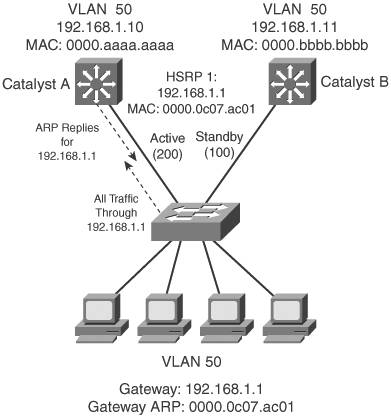
Without pre-emption, the active role cannot be given to any other router. HSRP Gateway AddressingEach router in an HSRP group has its own unique IP address assigned to an interface. This address is used for all routing protocol and management traffic initiated by or destined to the router. In addition, each router has a common gateway IP address, the virtual router address, that is kept alive by HSRP. This address also is referred to as the HSRP address or the standby address. Clients can point to that virtual router address as their default gateway, knowing that a router always keeps that address active. Keep in mind that the actual interface address and the virtual (standby) address must be configured to be in the same IP subnet. You can assign the HSRP address with the following interface command: Switch(config-if)# standby group ip ip-address [secondary] When HSRP is used on an interface that has secondary IP addresses, you can add the secondary keyword so that HSRP can provide a redundant secondary gateway address. Naturally, each router keeps a unique MAC address for its interface. This MAC address always is associated with the unique IP address configured on the interface. For the virtual router address, HSRP defines a special MAC address of the form 0000.0c07.acxx, where xx represents the HSRP group number as a two-digit hex value. For example, HSRP Group 1 appears as 0000.0c07.ac01, HSRP Group 16 appears as 0000.0c07.ac10, and so on. Figure 14-1 shows a simple network in which two multilayer switches use HSRP Group 1 to provide the redundant gateway address 192.168.1.1. CatalystA is the active router, with priority 200, and answers the ARP request for the gateway address. Because CatalystB is in the standby state, it never is used for traffic sent to 192.168.1.1. Instead, only CatalystA performs the gateway routing function, and only its uplink to the access layer is utilized. Figure 14-1. Typical HSRP Scenario with One HSRP Group Example 14-1 shows the configuration commands you can use on CatalystA. CatalystB would be configured similarly, except that its HSRP priority would use the default value of 100. Example 14-1. Configuring an HSRP Group on a SwitchCatalystA(config)# interface vlan 50 CatalystA(config-if)# ip address 192.168.1.10 255.255.255.0 CatalystA(config-if)# standby 1 priority 200 CatalystA(config-if)# standby 1 preempt CatalystA(config-if)# standby 1 ip 192.168.1.1 Load Balancing with HSRPConsider a network in which HSRP is used on two distribution switches to provide a redundant gateway address for access-layer users. Only one of the two becomes the active HSRP router; the other remains in standby. All the users send their traffic to the active router, over the uplink to the active router. The standby router and its uplink essentially sit idle until a router failure occurs. Load balancing traffic across two uplinks to two HSRP routers with a single HSRP group is not possible. Then how is it possible to load-balance with HSRP? The trick is to use two HSRP groups:
In this way, two different virtual router or gateway addresses can be used simultaneously. The rest of the trick is to make each switch function as the standby router for its partner's HSRP group. In other words, each router is active for one group and standby for the other group. The clients or end users also must have their default gateway addresses configured as one of the two virtual HSRP group addresses. Figure 14-2 presents this scenario. Now, CatalystA is not only the active router for HSRP Group 1 (192.168.1.1), but it is also the standby router for HSRP Group 2 (192.168.1.2). CatalystB is configured similarly, but with its roles reversed. The remaining step is to configure half of the client PCs with the HSRP Group 1 virtual router address and the other half with the Group 2 address. This makes load balancing possible and effective. Each half of the hosts uses one switch as its gateway over one uplink. Figure 14-2. Load Balancing with Two HSRP Groups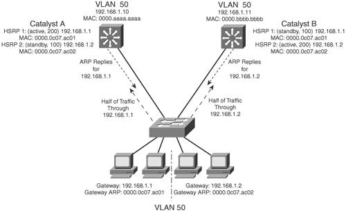 Example 14-2 shows the configuration commands you can use for the scenario shown in Figure 14-2. Example 14-2. Configuring Load Balancing Between HSRP GroupsCatalystA(config)# interface vlan 50 CatalystA(config-if)# ip address 192.168.1.10 255.255.255.0 CatalystA(config-if)# standby 1 priority 200 CatalystA(config-if)# standby 1 preempt CatalystA(config-if)# standby 1 ip 192.168.1.1 CatalystA(config-if)# standby 1 authentication MyKey CatalystA(config-if)# standby 2 priority 100 CatalystA(config-if)# standby 2 ip 192.168.1.2 CatalystA(config-if)# standby 2 authentication MyKey CatalystB(config)# interface vlan 50 CatalystB(config-if)# ip address 192.168.1.11 255.255.255.0 CatalystB(config-if)# standby 1 priority 100 CatalystB(config-if)# standby 1 ip 192.168.1.1 CatalystB(config-if)# standby 1 authentication MyKey CatalystB(config-if)# standby 2 priority 200 CatalystB(config-if)# standby 2 preempt CatalystB(config-if)# standby 2 ip 192.168.1.2 CatalystB(config-if)# standby 2 authentication MyKey You can use the following command to display information about the status of one or more HSRP groups and interfaces: Router# show standby [brief] [vlan vlan-id | type mod/num] Based on the configuration in Example 14-2, the output in Example 14-3 shows that the CatalystA switch is the active router for HSRP group 1 and the standby router for HSRP group 2 on interface VLAN 50. Example 14-3. Displaying the HSRP Router Role of a Switch: CatalystACatalystA# show standby vlan 50 brief P indicates configured to preempt. | Interface Grp Prio P State Active addr Standby addr Group addr Vl50 1 200 P Active local 192.168.1.11 192.168.1.1 Vl50 2 100 Standby 192.168.1.11 local 192.168.1.2 CatalystA# CatalystA# show standby vlan 50 Vlan50 - Group 1 Local state is Active, priority 200, may preempt Hellotime 3 sec, holdtime 10 sec Next hello sent in 2.248 Virtual IP address is 192.168.1.1 configured Active router is local Standby router is 192.168.1.11 expires in 9.860 Virtual mac address is 0000.0c07.ac01 Authentication text "MyKey" 2 state changes, last state change 00:11:58 IP redundancy name is "hsrp-Vl50-1" (default) Vlan50 - Group 2 Local state is Standby, priority 100 Hellotime 3 sec, holdtime 10 sec Next hello sent in 1.302 Virtual IP address is 192.168.1.2 configured Active router is 192.168.1.11, priority 200 expires in 7.812 Standby router is local Authentication text "MyKey" 4 state changes, last state change 00:10:04 IP redundancy name is "hsrp-Vl50-2" (default) CatalystA# The output from CatalystB in Example 14-4 shows that it has inverted roles from CatalystA for HSRP groups 1 and 2. Example 14-4. Displaying the HSRP Router Role of a Switch: CatalystBCatalystB#show standby vlan 50 brief P indicates configured to preempt. | Interface Grp Prio P State Active addr Standby addr Group addr Vl50 1 100 Standby 192.168.1.10 local 192.168.1.1 Vl50 2 200 P Active local 192.168.1.10 192.168.1.2 CatalystB# CatalystB#show standby vlan 50 Vlan50 - Group 1 Local state is Standby, priority 100 Hellotime 3 sec, holdtime 10 sec Next hello sent in 0.980 Virtual IP address is 192.168.1.1 configured Active router is 192.168.1.10, priority 200 expires in 8.128 Standby router is local Authentication text "MyKey" 1 state changes, last state change 00:01:12 IP redundancy name is "hsrp-Vl50-1" (default) Vlan50 - Group 2 Local state is Active, priority 200, may preempt Hellotime 3 sec, holdtime 10 sec Next hello sent in 2.888 Virtual IP address is 192.168.1.2 configured Active router is local Standby router is 192.168.1.10 expires in 8.500 Virtual mac address is 0000.0c07.ac02 Authentication text "MyKey" 1 state changes, last state change 00:01:16 CatalystB# Virtual Router Redundancy ProtocolThe Virtual Router Redundancy Protocol (VRRP) is a standards-based alternative to HSRP, defined in IETF standard RFC 2338. VRRP is so similar to HSRP that you need to learn only slightly different terminology and a couple of slight functional differences. When you understand HSRP operation and configuration, you also will understand VRRP. This section is brief, highlighting only the differences between HSRP and VRRP.
Note VRRP sends its advertisements to the multicast destination address 224.0.0.18 (VRRP), using IP protocol 112. VRRP was introduced in Cisco IOS Software Release 12.0(18)ST for routers. At press time, VRRP is available only for the Catalyst 6500 Supervisor 2 (Cisco IOS Software Release 12.2[9]ZA or later) and Supervisor 720 (Cisco IOS Software Release 12.2[17a]SX4 or later). To configure VRRP, use the interface-configuration commands documented in Table 14-2.
As an example, the load-balancing scenario shown in Figure 14-2 is implemented using VRRP. You would use the configuration commands in Example 14-5 on the two Catalyst switches. Example 14-5. Configuring Load Balancing with VRRPCatalystA(config)# interface vlan 50 CatalystA(config-if)# ip address 192.168.1.10 255.255.255.0 CatalystA(config-if)# vrrp 1 priority 200 CatalystA(config-if)# vrrp 1 ip 192.168.1.1 CatalystA(config-if)# vrrp 2 priority 100 CatalystA(config-if)# no vrrp 2 preempt CatalystA(config-if)# vrrp 2 ip 192.168.1.2 ___________________________________________________________________ CatalystB(config)# interface vlan 50 CatalystB(config-if)# ip address 192.168.1.10 255.255.255.0 CatalystB(config-if)# vrrp 1 priority 100 CatalystA(config-if)# no vrrp 1 preempt CatalystB(config-if)# vrrp 1 ip 192.168.1.1 CatalystB(config-if)# vrrp 2 priority 200 CatalystB(config-if)# vrrp 2 ip 192.168.1.2 You can use the following command to display information about VRRP status on one or more interfaces: Switch# show vrrp [brief]Example 14-6 shows this command executed on both CatalystA and CatalystB, with the output showing the alternating roles for the two VRRP groups configured in Example 14-5. Example 14-6. Displaying Switch Roles for VRRP Load BalancingCatalystA# show vrrp brief Interface Grp Pri Time Own Pre State Master addr Group addr Vlan50 1 200 3218 Y Master 192.168.1.10 192.168.1.1 Vlan50 2 100 3609 Backup 192.168.1.11 192.168.1.2 CatalystA# _______________________________________________________________________________ CatalystB# show vrrp brief Interface Grp Pri Time Own Pre State Master addr Group addr Vlan50 1 100 3609 Backup 192.168.1.10 192.168.1.1 Vlan50 2 200 3218 Y Master 192.168.1.11 192.168.1.2 CatalystB# Table 14-3 compares the detailed VRRP status between the CatalystA and CatalystB switches.
Gateway Load Balancing ProtocolYou should now know how both HSRP and VRRP can effectively provide a redundant gateway (virtual router) address. You can accomplish load balancing by configuring only multiple HSRP/ VRRP groups to have multiple virtual router addresses. More manual configuration is needed so that the client machines are divided among the virtual routers. Each group of clients must point to the appropriate virtual router. This makes load balancing somewhat labor-intensive, having a more or less fixed, or static, behavior. The Gateway Load Balancing Protocol (GLBP) is a Cisco-proprietary protocol designed to overcome the limitations of existing redundant router protocols. Some of the concepts are the same as with HSRP/VRRP, but the terminology is different and the behavior is much more dynamic and robust. Note GLBP was introduced in Cisco IOS Software Release 12.2(14)S for routers. At press time, GLBP is available only for the Catalyst 6500 Supervisor 2 with IOS Release 12.2(14)SY4 or later, and Supervisor 720 with IOS Release 12.2(17a)SX4 switch platforms. To provide a virtual router, multiple switches (routers) are assigned to a common GLBP group. Instead of having just one active router performing forwarding for the virtual router address, all routers in the group can participate and offer load balancing by forwarding a portion of the overall traffic. The advantage is that none of the clients has to be pointed toward a specific gateway address; they can all have the same default gateway set to the virtual router IP address. The load balancing is provided completely through the use of virtual router MAC addresses in ARP replies returned to the clients. As a client sends an ARP request looking for the virtual router address, GLBP sends back an ARP reply with the virtual MAC address of a selected router in the group. The result is that all clients use the same gateway address but have differing MAC addresses for it. Active Virtual GatewayThe trick behind this load balancing lies in the GLBP group. One router is elected the active virtual gateway (AVG). This router has the highest priority value, or the highest IP address in the group, if there is no highest priority. The AVG answers all ARP requests for the virtual router address. Which MAC address it returns depends upon which load-balancing algorithm it is configured to use. In any event, the virtual MAC address supported by one of the routers in the group is returned. The AVG also assigns the necessary virtual MAC addresses to each of the routers participating in the GLBP group. Up to four virtual MAC addresses can be used in any group. Each of these routers is referred to as an active virtual forwarder (AVF), forwarding traffic received on its virtual MAC address. Other routers in the group serve as backup or secondary virtual forwarders, in case the AVF fails. The AVG also assigns secondary roles. Assign the GLBP priority to a router with the following interface-configuration command: Switch(config-if)# glbp group priority level GLBP group numbers range from 0 to 1023. The router priority can be 1 to 255 (255 is the highest priority), defaulting to 100. As with HSRP, another router cannot take over an active role until the current active router fails. GLBP does allow a router to pre-empt and become the AVG if it has a higher priority than the current AVG. Use the following command to enable pre-empting and to set a time delay before pre-empting begins: Switch(config-if)# glbp group preempt [delay minimum seconds] Routers participating in GLBP must monitor each other's presence so that another router can assume the role of a failed router. To do this, the AVG sends periodic hello messages to each of the other GLBP peers. In addition, it expects to receive hello messages from each of them. Hello messages are sent at hellotime intervals, with a default of 3 seconds. If hellos aren't received from a peer within a holdtime, defaulting to 10 seconds, that peer is presumed to have failed. You can adjust the GLBP timers with the following interface-configuration command: Switch(config-if)# glbp group timers [msec] hellotime [msec] holdtime The timer values normally are given in seconds, unless they are preceded by the msec keyword, to indicate milliseconds. The hellotime can range from 1 to 60 seconds or from 50 to 60,000 milliseconds. The holdtime must be greater than the hellotime and can go up to 180 seconds or 180,000 milliseconds. You always should make the holdtime at least three times greater than the hellotime, to give some tolerance to missed or delayed hellos from a functional peer. Tip Although you can use the previous command to configure the GLBP timers on each peer router, it isn't necessary. Instead, just configure the timers on the router you have identified as the AVG. The AVG will advertise the timer values it is using, and every other peer will learn those values if they have not already been explicitly set. Active Virtual ForwarderBy default, GLBP uses the periodic hello messages to detect AVF failures, too. Each router within a GLBP group must send hellos to every other GLBP peer. Hellos also are expected from every other peer. For example, if hellos from the AVF are not received by the AVG before its holdtime timer expires, the AVG assumes that the current AVF has failed. The AVG then assigns the AVF role to another router. Naturally, the router that is given the new AVF role might already be an AVF for a different virtual MAC address. Although a router can masquerade as two different virtual MAC addresses to support the two AVF functions, it doesn't make much sense to continue doing that for a long period of time. The AVG maintains two timers that help resolve this condition. The redirect timer is used to determine when the AVG will stop using the old virtual MAC address in ARP replies. The AVF corresponding to the old address continues to act as a gateway for any clients that try to use it. When the timeout timer expires, the old MAC address and the virtual forwarder using it are flushed from all the GLBP peers. The AVG assumes that the previously failed AVF will not return to service, so the resources assigned to it must be reclaimed. At this point, clients still using the old MAC address in their ARP caches must refresh the entry to obtain the new virtual MAC address. The redirect timer defaults to 600 seconds (10 minutes) and can range from 0 to 3600 seconds (1 hour). The timeout timer defaults to 14,400 seconds (4 hours) and can range from 700 to 64,800 seconds (18 hours). You can adjust these timers with the following interface-configuration command: Switch(config-if)# glbp group timers redirect redirect timeout GLBP also can use a weighting function to determine which router becomes the AVF for a virtual MAC address in a group. Each router begins with a maximum weight value (1 to 254). As specific interfaces go down, the weight is decreased by a configured amount. GLBP uses thresholds to determine when a router can and cannot be the AVF. If the weight falls below the lower threshold, the router must give up its AVF role. When the weight rises above the upper threshold, the router can resume its AVF role. By default, a router receives a maximum weight of 100. If you want to make a dynamic weighting adjustment, GLBP must know which interfaces to track and how to adjust the weight. You first must define an interface as a tracked object with the following global configuration command: Switch(config)# track object-number interface type mod/num {line-protocol | ip routing} The object-number is an arbitrary index (1 to 500) that is used for weight adjustment. The condition that triggers an adjustment can be line-protocol (the interface line protocol is up) or ip routing (IP routing is enabled, the interface has an IP address, and the interface is up). Next, you must define the weighting thresholds for the interface with the following interface-configuration command: Switch(config-if)# glbp group weighting maximum [lower lower] [upper upper] The maximum weight can range from 1 to 254 (default 100). The upper (default maximum) and lower (default 1) thresholds define when the router can and cannot be the AVF, respectively. Finally, you must configure GLBP to know which objects to track so that the weighting can be adjusted with the following interface-configuration command: Switch(config-if)# glbp group weighting track object-number [decrement value] When the tracked object fails, the weighting is decremented by value (1 to 254, default 10). Likewise, a router that might serve as an AVF cannot pre-empt another when it has a higher weight value. GLBP Load BalancingThe AVG establishes load balancing by handing out virtual router MAC addresses to clients in a deterministic fashion. Naturally, the AVG first must inform the AVFs in the group of the virtual MAC address that each should use. Up to four virtual MAC addresses, assigned in sequential order, can be used in a group. You can use one of the following load-balancing methods in a GLBP group:
On the AVG router (or its successors), use the following interface-configuration command to define the method: Switch(config-if)# glbp group load-balancing [round-robin | weighted | host-dependent] Enabling GLBPTo enable GLBP, you must assign a virtual IP address to the group by using the following interface-configuration command: Switch(config-if)# glbp group ip [ip-address [secondary]] If the ip-address is not given in the command, it is learned from another router in the group. However, if this router is to be the AVG, you must explicitly configure the IP address; otherwise, no other router knows what the value should be. Figure 14-3 shows a typical network in which three multilayer switches are participating in a common GLBP group. CatalystA is elected the AVG, so it coordinates the entire GLBP process. The AVG answers all ARP requests for the virtual router 192.168.1.1. It has identified itself, CatalystB, and CatalystC as AVFs for the group. Figure 14-3. Multilayer Switches in a GLBP Group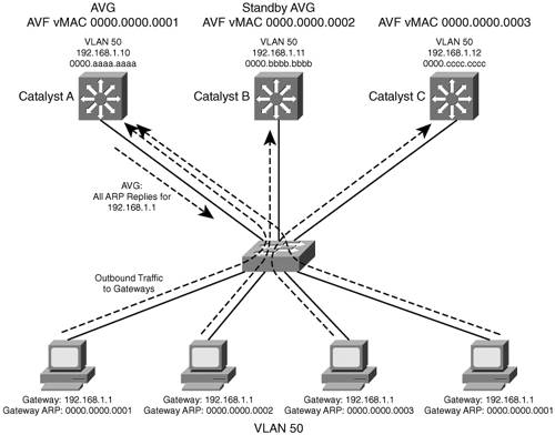 In this figure, round-robin load balancing is being used. Each of the client PCs looks for the virtual router address in turn, from left to right. Each time the AVG replies, the next sequential virtual MAC address is sent back to a client. After the fourth PC sends a request, all three virtual MAC addresses (and AVF routers) have been used, so the AVG cycles back to the first virtual MAC address. Notice that only one GLBP group has been configured, and all clients know of only one gateway IP address: 192.168.1.1. However, all uplinks are being utilized, and all routers are proportionately forwarding traffic. Redundancy is also inherent in the GLBP group: CatalystA is the AVG, but the next-highest priority router can take over if the AVG fails. All routers have been given an AVF role for a unique virtual MAC address in the group. If one AVF fails, some clients remember the last-known virtual MAC address that was handed out. Therefore, another of the routers also takes over the AVF role for the failed router, causing the virtual MAC address to remain alive at all times. Figure 14-4 shows how these redundancy features react when the current active AVG fails. Before its failure, CatalystA was the AVG because of its higher GLBP priority. After it failed, CatalystB became the AVG, answering ARP requests with the appropriate virtual MAC address for gateway 192.168.1.1. CatalystA also had been acting as an AVF, participating in the gateway load balancing. CatalystB also picks up this responsibility, using its virtual MAC address 0000.0000.0002 along with the one CatalystA had been using, 000.0000.0001. Therefore, any hosts that know the gateway by any of its virtual MAC addresses still can reach a live gateway or AVF. Figure 14-4. How GLBP Reacts to a Component Failure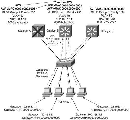 You can implement the scenario shown in Figures 14-3 and 14-4 with the configuration commands in Example 14-7 for CatalystA, CatalystB, and CatalystC, respectively. Example 14-7. Configuring GLBP Load BalancingCatalystA(config)# interface vlan 50 CatalystA(config-if)# ip address 192.168.1.10 255.255.255.0 CatalystA(config-if)# glbp 1 priority 200 CatalystA(config-if)# glbp 1 preempt CatalystA(config-if)# glbp 1 ip 192.168.1.1 ____________________________________________________________________ CatalystB(config)# interface vlan 50 CatalystB(config-if)# ip address 192.168.1.11 255.255.255.0 CatalystB(config-if)# glbp 1 priority 150 CatalystB(config-if)# glbp 1 preempt CatalystB(config-if)# glbp 1 ip 192.168.1.1 ____________________________________________________________________ CatalystC(config)# interface vlan 50 CatalystC(config-if)# ip address 192.168.1.12 255.255.255.0 CatalystC(config-if)# glbp 1 priority 100 CatalystC(config-if)# glbp 1 ip 192.168.1.1 You can verify GLBP operation with the show glbp [brief] command, as demonstrated in Example 14-8. With the brief keyword, the GLBP roles are summarized showing the interface, GLBP group number (Grp), virtual forwarder number (Fwd), GLBP priority (Pri), state, and addresses. Example 14-8. Verifying GLBP OperationCatalystA# show glbp brief Interface Grp Fwd Pri State Address Active router Standby router Vl50 1 - 200 Active 192.168.1.1 local 192.168.1.11 Vl50 1 1 7 Active 0007.b400.0101 local - Vl50 1 2 7 Listen 0007.b400.0102 192.168.1.11 - Vl50 1 3 7 Listen 0007.b400.0103 192.168.1.13 - CatalystA# _____________________________________________________________________________________ CatalystB# show glbp brief Interface Grp Fwd Pri State Address Active router Standby router Vl50 1 - 150 Standby 192.168.1.1 192.168.1.10 local Vl50 1 1 7 Listen 0007.b400.0101 192.168.1.10 - Vl50 1 2 7 Active 0007.b400.0102 local - Vl50 1 3 7 Listen 0007.b400.0103 192.168.1.13 - CatalystB# _____________________________________________________________________________________ CatalystC# show glbp brief Interface Grp Fwd Pri State Address Active router Standby router Vl50 1 - 100 Listen 192.168.1.1 192.168.1.10 192.168.1.11 Vl50 1 1 7 Listen 0007.b400.0101 192.168.1.10 - Vl50 1 2 7 Listen 0007.b400.0102 192.168.1.11 - Vl50 1 3 7 Active 0007.b400.0103 local - CatalystC# Notice that CatalystA is shown to be the AVG because it has a dash in the Fwd column and is in the Active state. It also is acting as AVF for virtual forwarder number 1. Because the GLBP group has three routers, there are three virtual forwarders and virtual MAC addresses. CatalystA is in the Listen state for forwarders number 2 and 3, waiting to be given an active role in case one of those AVFs fails. CatalystB is shown to have the Standby role, waiting to take over in case the AVG fails. It is the AVF for virtual forwarder number 2. Finally, CatalystC has the lowest GLBP priority, so it stays in the Listen state waiting for the active or standby AVG to fail. It is also the AVF for virtual forwarder number 3. You also can display more detailed information about the GLBP configuration and status by omitting the brief keyword. Example 14-9 shows this output on the AVG router. Because this is the AVG, the virtual forwarder roles it has assigned to each of the routers in the GLBP group also are shown. Example 14-9. Displaying Detailed GLBP Configuration and Status InformationCatalystA# show glbp Vlan50 - Group 1 State is Active 7 state changes, last state change 03:28:05 Virtual IP address is 192.168.1.1 Hello time 3 sec, hold time 10 sec Next hello sent in 1.672 secs Redirect time 600 sec, forwarder time-out 14400 sec Preemption enabled, min delay 0 sec Active is local Standby is 192.168.1.11, priority 150 (expires in 9.632 sec) Priority 200 (configured) Weighting 100 (default 100), thresholds: lower 1, upper 100 Load balancing: round-robin There are 3 forwarders (1 active) Forwarder 1 State is Active 3 state changes, last state change 03:27:37 MAC address is 0007.b400.0101 (default) Owner ID is 00d0.0229.b80a Redirection enabled Preemption enabled, min delay 30 sec Active is local, weighting 100 Forwarder 2 State is Listen MAC address is 0007.b400.0102 (learnt) Owner ID is 0007.b372.dc4a Redirection enabled, 598.308 sec remaining (maximum 600 sec) Time to live: 14398.308 sec (maximum 14400 sec) Preemption enabled, min delay 30 sec Active is 192.168.1.11 (primary), weighting 100 (expires in 8.308 sec) Forwarder 3 State is Listen MAC address is 0007.b400.0103 (learnt) Owner ID is 00d0.ff8a.2c0a Redirection enabled, 599.892 sec remaining (maximum 600 sec) Time to live: 14399.892 sec (maximum 14400 sec) Preemption enabled, min delay 30 sec Active is 192.168.1.13 (primary), weighting 100 (expires in 9.892 sec) CatalystA# Verifying Gateway RedundancyTo verify the operation of the features discussed in this chapter, you can use the commands listed in Table 14-4. In particular, look for the active, standby, or backup routers in use.
Redundancy Within a Switch ChassisThe router or gateway redundancy protocols, such as HSRP, VRRP, and GLBP, can provide high availability only for the default gateway addresses. If one of the redundant gateway routers fails, another can pick up the pieces and appear to be the same gateway address. But what happens to the devices that are connected directly to the router that fails? If the switching or routing engine fails, packets probably will not get routed and interfaces will go down. Some Cisco switches have the capability to provide redundancy for the supervisor engine itself. This is accomplished by having redundant hardware in place within a switch chassis, ready to take over during a failure. You also should consider switch power as a vital part of achieving high availability. For example, if a switch has a single power supply and a single power cord, the whole switch will fail if the power supply fails or if the power cord accidentally is unplugged. Some switch platforms can have multiple power supplies; if one power supply fails, another immediately takes over the load. Redundant Switch SupervisorsModular switch platforms such as the Catalyst 4500R and 6500 can accept two supervisor modules installed in a single chassis. The first supervisor module to successfully boot up becomes the active supervisor for the chassis. The other supervisor remains in a standby role, waiting for the active supervisor to fail. The active supervisor always is allowed to boot up and become fully initialized and operational. All switching functions are provided by the active supervisor. The standby supervisor, however, is allowed to boot up and initialize only to a certain level. When the active module fails, the standby module can proceed to initialize any remaining functions and take over the active role. Redundant supervisor modules can be configured in several modes. The redundancy mode affects how the two supervisors handshake and synchronize information. In addition, the mode limits the standby supervisor's state of readiness. The more ready the standby module is allowed to become, the less initialization and failover time will be required. You can use the following redundancy modes on Catalyst switches:
Tip Sometimes the redundancy mode terminology can be confusing. In addition to the RPR, RPR+, and SSO terms, you might see Single Router Mode (SRM) and Dual Router Mode (DRM). SRM simply means that two route processors (integrated into the supervisors) are being used, but only one of them is active at any time. In DRM, two route processors are active at all times. HSRP usually is used to provide redundancy in DRM. Although RPR and RPR+ have only one active supervisor, the route processor portion is not initialized on the standby unit. Therefore, SRM is not compatible with RPR or RPR+. SRM is inherent with SSO, which brings up the standby route processor. You usually will find the two redundancy terms together, as "SRM with SSO." Configuring the Redundancy ModeTable 14-5 details the redundancy modes you can configure on supported switch platforms.
Figure 14-5 shows how the supervisor redundancy modes compare with respect to the functions they perform. The shaded functions are performed as the standby supervisor initializes and then waits for the active supervisor to fail. When a failure is detected, the remaining functions must be performed in sequence before the standby supervisor can become fully active. Notice how the redundancy modes get progressively more initialized and ready to become active. Figure 14-5. Standby Supervisor Readiness as a Function of Redundancy Mode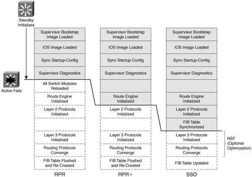 You can configure the supervisor redundancy mode by entering the redundancy-configuration mode with the following command: Router(config)# redundancyNext, select the redundancy mode with one of the following commands: Router(config-red)# mode {rpr | rpr-plus | sso} If you are configuring redundancy for the first time on the switch, you must enter the previous commands on both supervisor modules. When the redundancy mode is enabled, you will make all configuration changes on the active supervisor only. The running configuration is synchronized automatically from the active to the standby module. Tip If you configure RPR+ with the rpr-plus keyword, the supervisor attempts to bring up RPR+ with its peer module. The IOS images must be of exactly the same release before RPR+ will work. If the images differ, the supervisor automatically falls back to RPR mode instead. You can verify the redundancy mode and state of the supervisor modules by using the following command: Router# show redundancy statesThe output in Example 14-10 shows that the switch is using RPR+ and that the second supervisor module (denoted by unit ID 2 and "my state") holds the active role. The other supervisor module is in the standby state and is "HOT", meaning that it has initialized as far as the redundancy mode will allow. Example 14-10. Verifying Supervisor Module Redundancy Mode and StateRouter# show redundancy status my state = 13 -ACTIVE peer state = 8 -STANDBY HOT Mode = Duplex Unit = Secondary Unit ID = 2 Redundancy Mode (Operational) = Route Processor Redundancy Plus Redundancy Mode (Configured) = Route Processor Redundancy Plus Split Mode = Disabled Manual Swact = Enabled Communications = Up client count = 11 client_notification_TMR = 30000 milliseconds keep_alive TMR = 9000 milliseconds keep_alive count = 1 keep_alive threshold = 18 RF debug mask = 0x0 Router# Configuring Supervisor SynchronizationBy default, the active supervisor synchronizes its startup configuration and configuration register values with the standby supervisor. You also can specify other information that should be synchronized. First, use the following commands to enter the main-cpu configuration mode: Router(config)# redundancy Router(config-red)# main-cpu Then use the following command to specify the information that will be synchronized: Router(config-r-mc)# auto-sync {startupp-config | config-register | bootvar} You can repeat the command if you need to use more than one of the keywords. To return to the default, use the auto-sync standard command. Non-Stop ForwardingYou can enable another redundancy feature along with SSO on the Catalyst 4500R and 6500 (Supervisor 720 only). Non-Stop Forwarding (NSF) is an interactive method that focuses on quickly rebuilding the routing information base (RIB) table after a supervisor switchover. The RIB is used to generate the FIB table for CEF, which is downloaded to any switch modules or hardware that can perform CEF. Instead of waiting on any configured Layer 3 routing protocols to converge and rebuild the FIB, a router can use NSF to get assistance from other NSF-aware neighbors. The neighbors then can provide routing information to the standby supervisor, allowing the routing tables to be assembled quickly. In a nutshell, the Cisco-proprietary NSF functions must be built into the routing protocols on both the router that will need assistance and the router that will provide assistance. NSF is supported by the BGP, EIGRP, OSPF, and IS-IS routing protocols. NSF is available on the Catalyst 6500 Supervisor 720 (with the integrated MSFC3) and on the Catalyst 4500R Supervisor III, IV, and V running IOS Software Release 12.2(20)EWA or later. To configure NSF, you must add the commands in Table 14-6 to any routing protocol configuration on the switch.
Redundant Power SuppliesThe Cisco Catalyst 6500 and 4500R platforms can accept two power supply modules in a single chassis. The power supplies must be identical, having the same power input and maximum power output ratings. The switch can be configured to operate in one of two possible power modes:
By default, a switch is configured for redundant mode. If two power supplies are installed and functioning, they are managed as redundant replacements for each other. Both supplies are enabled and active, as if they were both supplying power. In fact, you probably won't be able to tell which supply is actually powering the switch until one of them is turned off or fails. You can display the current power configuration and status of a switch with the following command: Switch# show power [redundancy-mode | status | available | used | total] If you don't use any of the optional keywords, the resulting output yields all information about the system power. For instance, notice that the switch in Example 14-11 is in redundant mode and that both power supplies are operational. Example 14-11. Verifying Switch Redundant Mode and Power Supply Operational StatusSwitch# show power system power redundancy mode = redundant system power total = 1153.32 Watts (27.46 Amps @ 42V) system power used = 693.42 Watts (16.51 Amps @ 42V) system power available = 459.90 Watts (10.95 Amps @ 42V) Power-Capacity PS-Fan Output Oper PS Type Watts A @42V Status Status State ---- ------------------ ------- ------ ------ ------ ----- 1 WS-CAC-1300W 1153.32 27.46 OK OK on 2 WS-CAC-1300W 1153.32 27.46 OK OK on Pwr-Requested Pwr-Allocated Admin Oper Slot Card-Type Watts A @42V Watts A @42V State State ---- ------------------ ------- ------ ------- ------ ----- ----- 1 WS-X6K-SUP2-2GE 145.32 3.46 145.32 3.46 on on 2 - - 145.32 3.46 - - 3 WS-X6348-RJ45 100.38 2.39 100.38 2.39 on on 4 WS-X6516-GBIC 142.80 3.40 142.80 3.40 on on 5 WS-C6500-SFM 117.18 2.79 117.18 2.79 on on Switch# The show power command also displays information about the status of each switch module, the amount of power it has requested to receive, and the amount of power it is actually being budgeted. Most switch modules have a fixed power requirement, so the power requested and allocated values are equal. One important exception is any switch module that supplies inline power or PoE to end devices. These end devices can request a power budget when they initialize and can request a different budget at any later time. Cisco IP Telephones and wireless access points are good examples of this. Power requests are handled through Cisco Discovery Protocol (CDP) exchanges between the device and the switch. You can display the current power status of inline power switch ports with the show power inline command, as demonstrated in Example 14-12. Example 14-12. Verifying Inline Power Switch Port StatusSwitch# show power inline Interface Admin Oper Power Device (Watts) ---------- ----- ---------- ------- ------------------- Fa3/1 auto off 0 n/a Fa3/2 auto on 6.2 cisco AIR-AP1230B-A Fa3/3 auto on 6.2 cisco AIR-AP1230B-A Fa3/4 auto on 5.6 Cisco IP Phone 7905 Fa3/5 auto on 5.6 Cisco IP Phone 7905 Fa3/6 auto on 6.3 Cisco IP Phone 7940 Fa3/7 auto on 6.3 Cisco IP Phone 7940 Fa3/8 auto on 6.3 Cisco IP Phone 7940 Fa3/9 auto off 0 n/a Fa3/10 auto on 6.3 Cisco IP Phone 7912 Fa3/11 auto off 0 n/a Fa3/12 auto on 6.3 Cisco IP Phone 7940 Fa3/13 auto on 6.3 Cisco IP Phone 7940 Fa3/14 auto on 6.3 Cisco IP Phone 7940 [output omitted]You can change the power supply mode by using the following command: Switch(config)# power redundancy-mode {redundant | combined} You also can control the power that is being supplied to a switch module. For example, if you want to remove a module for repair or relocation, you can disable its power before it is pulled out of the chassis. Use the following command to control the power to the module in chassis slot number slot: Switch(config)# [no] power enable module slot Without the no keyword, the module is powered on; include the no keyword to remove power from the module. |
EAN: 2147483647
Pages: 177
- Challenging the Unpredictable: Changeable Order Management Systems
- The Second Wave ERP Market: An Australian Viewpoint
- Enterprise Application Integration: New Solutions for a Solved Problem or a Challenging Research Field?
- Intrinsic and Contextual Data Quality: The Effect of Media and Personal Involvement
- Development of Interactive Web Sites to Enhance Police/Community Relations