2-1 Ethernet Interfaces
-
All Ethernet interfaces are based on the IEEE 802.3 standard. Fast Ethernet is based on the IEEE 802.3u standard, and Gigabit Ethernet is based on the IEEE 802.3z standard.
-
Ethernet interfaces support 10 Mbps media with AUI or 10BaseT connections.
-
Fast Ethernet interfaces support 10/100 Mbps media with 100BaseTX or 100BaseFX (fiber) connections.
-
Gigabit Ethernet interfaces support 1 Gbps media with 1000BaseSX, 1000BaseLX/LH, and 1000BaseZX GBIC modules (all fiber- optic media).
-
Fast Ethernet and Gigabit Ethernet interfaces support single subnets or can support two types of VLAN trunking. See Section 2-5 for more information.
Configuration
-
(Optional) Select an Ethernet encapsulation:
(interface) encapsulation { arpa sap snap }
Ethernet frames can be encapsulated as ARPA Ethernet version 2.0 ( arpa, the default), SAP IEEE 802.3 ( sap ), or SNAP for IEEE 802.2 media ( snap ).
-
(Optional) Select the media type:
(interface) media-type { aui 10baset mii 100basex }
The media type can be configured on some router platforms where more than one Ethernet or Fast Ethernet connector is provided. The connector can be aui (15-pin), 10baset (RJ-45), mii (Media-Independent Interface), or 100basex (RJ-45 or SC fiber).
-
(Fast Ethernet only) Specify the interface speed:
(interface) speed { 10 100 auto }
The speed can be locked to 10 Mbps, 100Mbps, or auto-negotiation .
-
(Fast or Gigabit Ethernet only) Specify the duplex mode:
(interface) duplex { full half auto }
The interface can be locked to full- or half-duplex (the default) or auto-negotiation.
-
(Optional) Configure Fast EtherChannel.
-
Assign an interface to a channel group :
(interface) channel-group group
Up to four Fast Ethernet interfaces can be bundled under a common group number. No Layer 3 addresses should be configured on any of the bundled interfaces. All Layer 3 traffic is distributed across the individual interfaces within the bundle, and non-Layer 3 traffic is sent across the first link in the bundle.
-
Assign network addresses to the bundle:
(global) interface port-channel group (interface) ...
Layer 3 addresses or bridge groups can be assigned to the bundle as a whole. The port channel acts as the routed interface rather than the individual physical interfaces.
-
Example
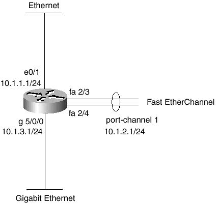
An Ethernet interface, two Fast Ethernet interfaces, and one Gigabit Ethernet interface are all configured for use. The Ethernet and Gigabit Ethernet interfaces are given IP addresses. The two Fast Ethernet interfaces are configured as a single Fast EtherChannel bundle (channel group 1). The bundle, as interface port channel 1, is configured with an IP address. Refer to the network diagram shown in Figure 2-1.
Figure 2-1. Network Diagram for the Ethernet Interface Example

interface ethernet 0/1 ip address 10.1.1.1 255.255.255.0 interface fastethernet 2/3 speed auto duplex auto channel-group 1 no ip address interface fastethernet 2/4 speed auto duplex auto channel-group 1 no ip address interface port-channel 1 ip address 10.1.2.1 255.255.255.0 interface gigabitethernet 5/0/0 ip address 10.1.3.1 255.255.255.0 duplex full
EAN: N/A
Pages: 185
- Structures, Processes and Relational Mechanisms for IT Governance
- Assessing Business-IT Alignment Maturity
- Measuring and Managing E-Business Initiatives Through the Balanced Scorecard
- A View on Knowledge Management: Utilizing a Balanced Scorecard Methodology for Analyzing Knowledge Metrics
- Measuring ROI in E-Commerce Applications: Analysis to Action