2-2. Switched Campus Network Designs When you design a switched network, you must consider many things. Adding to or redesigning a large enterprise or campus network can seem complex or overwhelming. There is an accepted, organized approach to switched network design that can simplify the design process, as well as make the network more efficient and scalable. This section is organized as a quick reference "checklist" of guidelines, rules of thumb, and ideas to help you think through the overall network architecture and configuration. Many of the checklist items include a reference to the appropriate sections of this book that deal with the switch features. 1. | Segment LANs into the smallest collision domains possible by using LAN switches.
| 2. | Organize your enterprise network into a hierarchical structure.
A network designed around a layered structure gives the foundation for predictable behavior, consistent latency (number of switch hops) from anywhere in the network, and scalability. If the network needs to be expanded, you can add more switch blocks into the existing structure.
Figure 2-1 shows the basic network hierarchy divided into three distinct layers:
- - Access layer Consists of switches that connect to the end users
- - Distribution layer Consists of switches that aggregate traffic from the access layer
- - Core layer Consists of switches that aggregate traffic from the distribution layers
Figure 2-1. Layers of a Hierarchical Network Design 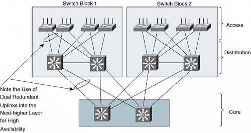
TIP In small to medium sized enterprise networks, the distribution layer can be omitted. The access layer switches uplink directly into the core layer. This is referred to as a collapsed core design. To provide high availability, each switch in a network layer should have dual or redundant uplinks to two switches in the next higher layer. In the event of a link failure or the failure of an entire switch, the extra uplink can be quickly used. The uplink failover is handled by the Spanning Tree Protocol (STP) at Layer 2, or by routing protocols at Layer 3.
| 3. | Place switching functionality at each layer of the hierarchy.
- - Access Switches at this layer generally have a high port density, lower cost, features that address user access or security, and several high-speed uplink ports. Usually, Layer 2 switching is sufficient, although Layer 3 switching can provide higher availability for applications such as IP telephony.
- - Distribution Distribution switches have a port density made up of high-speed ports, and offer higher switching performance, ideally at Layer 3.
- - Core The core layer should be built from the highest performance switches in the network, aggregating traffic from the distribution switches. Layer 2 switches can be used effectively, although switching at Layer 3 adds higher availability and enhanced QoS. Usually, a dual-switch core layer is sufficient to support an entire enterprise.
| 4. | Identify resources in your network that serve common functions. These will become the modules or building blocks of your network design. Figure 2-2 shows some examples of these blocks and how they fit within the network hierarchy.
Figure 2-2. Modular Approach to a Campus Network Design 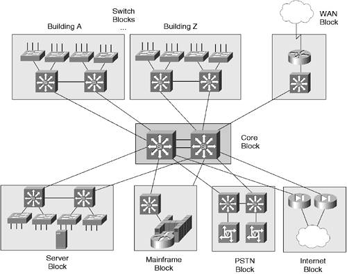
TIP The network in Figure 2-2 is shown with single uplinks to higher layers for simplicity. In a real network, you should always add dual redundant uplinks to two switches in the next higher network layer for the highest network availability. In this case, each access layer switch would have two uplinks to the two nearest distribution switches. In addition, each distribution switch in each block of the diagram would have two uplinks to the two core layer switches. In other words, the basic principles of Figure 2-1 should be applied to the enterprise layout of Figure 2-2. - - Server farms and mainframes These are called server blocks and mainframe blocks, respectively.
- - Internet access, e-commerce or extranet server farms, and firewall farms These are called an Internet block.
- - Remote access This is called a WAN block.
- - Telephony servers and gateways This is called a PSTN block.
- - Legacy networks (Token Ring, FDDI, and so on) This is very similar to the WAN block, using a router to provide connectivity to various network media types.
- - Common workgroups of users End users located in the same building, on the same floor, or in the same area of a floor are called switch blocks. A switch block typically groups access layer switches and the distribution switches to which they connect.
| 5. | Consider high availability or redundancy features that can be used in each network building block:
- a. Core
- If Layer 2 switches are used, don't create a spanning-tree loop by connecting the two core switches. - Be sure to identify and configure both primary and secondary root bridge switches for each VLAN. Typically, the root bridge should be placed close to the core layer. See section "7-2: STP Configuration." - If Layer 3 switches are used, connect the core switches with multiple links. See section "4-4: EtherChannel." - In a Layer 3 core, make use of Hot Standby Router Protocol (HSRP) to provide redundant gateway addresses. See section "8-6: Router Redundancy with HSRP." - Each core switch should connect to each distribution switch for full redundancy. If Layer 3 is not used in the core or distribution layers, use STP BackboneFast to reduce STP convergence time. See section "7-2: STP Configuration."
- b. Server block
- Use redundant uplinks into the distribution or core layer. Utilize STP UplinkFast (section "7-2: STP Configuration") or HSRP (section "8-6: Router Redundancy with HSRP") for fast failover. - Consider using dual network interface cards (NICs) in servers for redundancy. Connect the NICs into different switch cards or modules.
- c. Internet block
- Use Server Load Balancing to distribute traffic across multiple servers in a server farm. See section "10-1: SLB." - Use Firewall Load Balancing to distribute traffic across multiple firewalls in a firewall farm. See section "10-2: SLB Firewall Load Balancing."
- d. Switch blocks
- Each access layer switch has dual uplinks to two separate distribution switches. - Use STP UplinkFast on access layer switches to reduce uplink failover time. - Use STP PortFast on access layer ports to reduce startup time for end users. - To load balance across the access layer uplinks, adjust the STP parameters so that one access VLAN travels over one uplink while another VLAN travels over the other uplink (Layer 2 distribution layer). Otherwise, adjust the HSRP priorities in a Layer 3 distribution so that one distribution switch supports one access VLAN and the other distribution switch supports another VLAN. - If Layer 3 is used in the distribution layer, use passive interfaces toward the access layer where no other routers reside.
| 6. | Other considerations
- a. For each VLAN, configure an STP root bridge and a secondary root bridge as close to the core layer as possible. See section "7-2: STP Configuration."
- b. Broadcast domains
- Limit the size of broadcast domains by controlling the size of VLANs. It is permissible to extend VLANs anywhere in the network, but broadcast traffic will follow it. - Consider using broadcast suppression on switch ports. See section "11-1: Broadcast Suppression."
- c. VLAN Trunking Protocol (VTP)
- Configure VTP servers nearest the core layer. - Use VTP pruning or manually configure specific VLANs to be transported on trunks. This reduces the unnecessary broadcast traffic on the trunks.
- d. Scaling trunks
- Bundle multiple trunk links together into an EtherChannel. For fault tolerance, divide the EtherChannel across switch modules. See section "4-4: EtherChannel." - Do not configure trunk negotiation; use the "on" mode. See section "6-3: Trunking."
- e. QoS
- Configure QoS on every switch in your network. QoS must be properly supported end-to-end. See section "13-2: QoS Configuration." - Extend the QoS trust boundary to edge devices (IP phones, for example) that can provide trust. - Use policers to control non-mission-critical traffic flows.
- f. Redundant switch modules
- Consider using redundant supervisors in server farm switches where hosts are single-attached (one NIC). - If redundant uplinks are provided at each network layer, two physically separate switches will always provide redundancy. Use redundant supervisors in distribution or core layer switches where only single uplinks are available. - Use high-availability redundancy between supervisors in a chassis. Enable versioning so that the OS can be upgraded without a switch downtime. See section "3-5: Redundant Supervisors."
- g. Port security, authentication
- You can control the end-user MAC address or the number of users connected to an access layer switch port with port security. See section "11-4: Port Security." - Authenticate users at the access layer switch ports using 802.1x authentication. See section "11-2: AAA." - Control access to VLANs with VLAN ACLs. See section "11-5: VLAN ACLs."
|
|