| As previously mentioned, the FWSM is like the PIX Firewall/ASA in that they are both stateful, as discussed in detail in Chapter 3. The difference between the FWSM and PIX/ASA lies in the unique and complex architecture of the FWSM, which is discussed next. FWSM Architecture A block diagram (Figure 4-1) best explains the architecture of FWSM. Figure 4-1. FWSM Hardware Block Diagram 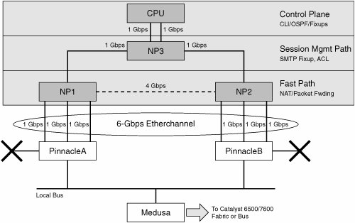
The different components of the FWSM that are pictured in Figure 4-1 are discussed in the sections that follow. Control Plane (CP) The FWSM module comprises primarily two elements: a CP, and a daughter card that hosts three Network Processors (NPs). Most of the memory-intensive tasks and complex operations are performed in the CP. The high performance is achieved by moving the frequently used simple tasks within the packet processing to the Network Processors. The CP is responsible for the following tasks: Layer 7 fixups Overall management of the blade Supervisory functions for each NP Running of routing protocols Preliminary compilation of the access rules before downloading them into the slow NP
CP has two Gigabit Ethernet ports connected to the Session Management Path NP (NP3), which is discussed next. You can verify the Gigabit Ethernet ports on the CP by executing the show nic command. Network Processors (NP) The Network Processor performs a subset of functions for the FWSM. Each NP has four Gigabit Ethernet interfaces. FWSM consists of the following three NPs: Session Management Path Network Processor (NP3) Session Management Path, which is shown in Figure 4-1, is referred to as NP3. NP3 connects to the CP using two Gigabit Ethernet portsports 3 and 4. Ports 1 and 2 are connected to the Fast Path Network Processors (NP1 and NP2). Fast Path Network processors (NP1 and NP2) The Fast Path NPs are referred to as NP1 and NP2. The fourth Gigabit Ethernet port of each NP connects to Port 1 and 2 of NP3. This leaves three available Gigabit Ethernet ports for each Fast Path NPNP1 and NP2to connect with the Catalyst 6500/7600 switching crossbar-SFM (offers 256 GBps) or backplane (offers 32 GBps). Hence, there are a total of six Gigabit Ethernet ports from Fast NPsNP1 and NP2 form an EtherChannel to connect with the Switch (cat6500/7600) bus/crossbar. The EtherChannel that is formed uses six Gigabit ports with Fast Path NPs.
EtherChannel For maximizing the efficiency of the six Gigabit Ethernet interfaces between the FastPath NPs and the Pinnacle, the switch software automatically bundles them together and creates an 802.1Q trunking Etherchannel connection. With a FWSM installed in slot 3, Example 4-1 shows the Etherchannel characteristics for that slot 3. Example 4-1. The Etherchannel Characteristics CAT6503# show etherchannel summary Flags: D - down P - in port-channel I - stand-alone s suspended H - Hot-standby (LACP only) R - Layer3 S Layer2 U - in use f failed to allocate aggregator Number of channel-groups in use: 1 Number of aggregators: 1 Group Port-channel Protocol Ports ------+-------------+-----------+---------------------------------------------- 272 Po272(SU) - Gi3/1(P) Gi3/2(P) Gi3/3(P) Gi3/4(P) Gi3/5(P) Gi3/6(P) CAT6503# show firewall module 3 state | include trunk Administrative Mode: trunk Operational Mode: trunk Vlans allowed on trunk: 1 CAT6503#
|
Figure 4-2 is a logical depiction of the connection between a Catalyst 6500/7600 and an FWSM located in slot 3. Figure 4-2. 6500/FWSM 6Gbps 802.1Q Etherchannel 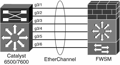
Traffic destined to the FWSM is subjected to the standard user-configurable Etherchannel traffic distribution algorithm. That algorithm determines which interface should be used to transmit traffic belonging to a given session. An interface in this case corresponds to one of the Gigabit Ethernet ports of either NP1 or NP2. Traffic is never load-balanced on a per-packet basis; rather, a session-based hash algorithm is used. Example 4-2 shows the user's choices for load-balancing traffic. Example 4-2. Choices for Etherchannel Load-Balancing Algorithm on the Switch CAT6503(config)# port-channel load-balance ? dst-ip Dst IP Addr dst-mac Dst Mac Addr dst-port Dst TCP/UDP Port ! This is the default setting for algorithm src-dst-ip Src XOR Dst IP Addr src-dst-mac Src XOR Dst Mac Addr src-dst-port Src-Dst TCP/UDP Port src-ip Src IP Addr src-mac Src Mac Addr src-port Src TCP/UDP Port CAT6503#
|
The FWSM is responsible for ensuring that the return traffic (from the FWSM back to the switch) follows the same path as the original traffic. If you see that an undesirable event occurs specifically to one port on the NP and not to the other, you can change the load-balancing algorithm on the cat6k, and see whether the pattern then looks different. Packet Flows In the preceding section, you learned the architectural details. This section presents the packet flows through the FWSM as illustrated in Figure 4-3. Figure 4-3. Packet Data Flows Through FWSM 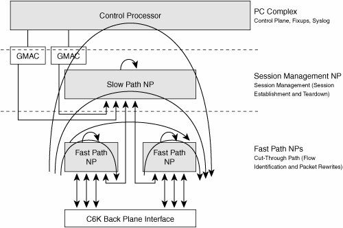
The following sequence illustrates the packet flow through the FWSM: 1. | The packets from the switch are forwarded from the Pinnacle buffer through one of the Etherchannel ports to the Fast Path.
| | | 2. | Fast Path Packet Flow
When the fast path receives a Dot1Q IP packet, the fast path performs the following actions on the packet:
It verifies if the destination MAC address is one of Firewall MAC Addresses / Broadcast / Multicast. It checks whether the destination IP is one of the firewall interface IP Addresses, and if so, sends the packets to Control Plane, for example, a Telnet session to the FWSM. If packets are routing packets (for example, RIP/OSPF packets), they are forwarded to the Control Plane. If the packets are fragmented, they are sent to the Virtual Reassembly Module. Non-TCP/UDP protocol packets are sent to the Session Management Path NP or the Control Plane (for example, ICMP packets). If packets are TCP/UDP packets, session lookup is performed. If the session lookup is successful (a matching entry found), the state retrieved from the session lookup will indicate what action should be taken with the packet. If the fragmentation flag was set, send the packet back to the "IP virtual reassembly" module. If the packet needs to be processed in the Fast Path, then rewrite the packet appropriately (NAT), and update the state if necessary (sequence Number / Window update / FIN Processing / Statistics / Time Stamps . . .). If the state is marked as an Intercepted Session / AAA Session (for updating the inactivity timer) and so on, send the packet to the Session Management Path NP (NP3). If SMTP fixup is required, send the packet to the Session Management Path (NP3); otherwise, for all other fixups, send the packet to the CP. If the Session lookup fails (a miss), then depending on the type of packet, actions will be taken accordingly. If the packet is not a SYN TCP packet, the packet is dropped. If it is an Internet Control Message Protocol (ICMP) and not an ECHO request from inside, the packet will be dropped (or an action will be taken depending on the ACL configured). If the packet is a TCP/UDP packet and is unable to find a session in the session table, the packet is forwarded to the Session Management Path NP.
| 2. | Session Management Path Packet Flow
A packet received from the Fast Path NPs will be processed in the Session Management Path NP (NP3) as follows:
If required, the packet will go through the access control list (ACL) checking, authentication, authorization, and accounting (AAA) and so on before it is sent to the CP for additional processing, such as fixup. Note that SMTP fixup is performed in the Session Management Path. The rest of the other traffic fixup is performed in the CP. If the packet received from the Fast Path is an existing session, the Fast Path NP will include the Session ID when sending it to the Session Management Path NP. The state in Session Management Path NP will be found, and the appropriate action will be taken (TCP intercept, SMTP fixup, AAA Timestamp Updates) based on the state information. A packet with no session (TCP SYN, UDP, Internet Control Message Protocol (ICMP) ECHO Request) will be processed on the Session Management Path (for example, the ACL will be checked for the packet). For additional processing, the packet will be sent to the CP. For example, the control connection of the FTP packet will be sent to the CP for the FTP fixup. If additional processing is not required by the CP (for example smtp fixup) the packet will be completely processed by the Session Management Path NP. Session information will be inserted, so that subsequent packets can be short-circuited.
| 3. | Control Plane (CP)
Control Plane performs all the intelligent and sophisticated activities. For example, the CP takes care of the fixup for Multi Channel Protocol, which helps in dynamically inspecting and opening up the necessary ports for the data connection. Control Plane also processes the traffic destined for it. The CP takes care of the overall NP managementsyslogging, routing and so on.
|
To understand the previous steps clearly, take an example of packet flow across the FWSM for FTP connection, as depicted in Figure 4-4. FTP connection requires packet processing on the CP and all network processors (both fast and Session Management NPs). This section walks through the packet flow of an FTP session when fixup is turned on for FTP as shown in Figure 4-4. Figure 4-4. Packet Flow for FTP Session 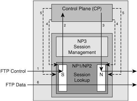
Step 1. | When the first FTP control packet arrives, the session lookup fails in Fast Path NP (NP1 or NP2), and the packet is directed to the Session Management Path (NP3).
| Step 2. | After passing the ACL tests in NP3, the packet is then forwarded to the CP for fixup, as this is an FTP packet.
| Step 3. | The CP processes the packet and sends it out through the NAT module.
| Step 4. | The CP inserts the control channel session entry in the fast path's session, and NAT modules indicating all the control channel packets should be directed to CP.
| Step 5. | On seeing the payload of the subsequent packets (PORT / PASV command), the CP inserts the necessary rule for allowing the data channel in the session module.
| Step 6. | All packets corresponding to the data channel are short-circuited in the fast path (NP1 & NP2).
|
|