7.3 Preparing the environment
|
| < Day Day Up > |
|
7.3 Preparing the environment
This section will provide information on how to prepare the environment to install GPFS software on the cluster nodes, getting them ready for GPFS customization and file system creation.
For the examples in this redbook, we will be using a six-nodes cluster. This cluster contains one management node, one storage node directly attached to storage enclosure, and four compute nodes named node001.cluster.com, node002.cluster.com, node003.cluster.com, and node004.cluster.com, referred to as node001, node002, node003, and node004. The operating system is Red Hat Linux 7.3 with kernel version 2.4.18-10smp.
7.3.1 Nodes preparation
GPFS software comes as an option for IBM ![]() Cluster 1350. In this chapter, we assume that you have your IBM
Cluster 1350. In this chapter, we assume that you have your IBM ![]() Cluster 1350 with CSM configured. We will take the advantage of CSM management tools such as cfmupdatenode, smsupdatenode, and dsh during GPFS installation. Refer to Chapter 6, "Cluster management with CSM" on page 149 for further information.
Cluster 1350 with CSM configured. We will take the advantage of CSM management tools such as cfmupdatenode, smsupdatenode, and dsh during GPFS installation. Refer to Chapter 6, "Cluster management with CSM" on page 149 for further information.
If you use the NSD network attached model for GPFS disk storage, you will need one storage attached server or so-called storage node. Refer to 5.4, "Special considerations for storage node installation" on page 146 on how to install the storage node.
7.3.2 Prerequisite software
Example 7-3 describes some prerequisite software that needs to be installed prior to GPFS installation. It is necessary to verify that your nodes have at least the specified level of the prerequisite software described below installed on each node in the GPFS cluster; some of the software is already installed prior to CSM installation.
| Packages from Red Hat 7.3 CD-ROM | Where to install |
|---|---|
| pdksh 5.2.14 | In all nodes |
| gcc-c++2.96-98 | In the management node |
| libstdc++-devel-2.96-98 | In the management node |
| gcc-2.96-98 | In the management node |
| glibc-devel-2.2.5-34 | In the management node |
| glibc-utils-2.2.5-34 | In the management node |
| glibc-kernheaders-2.4-7.14 | In the management node |
| cpp-2.96-98 | In the management node |
| kernel-source-<your kernel version> | In the management node |
7.3.3 Prepare kernel source file for GPFS and Myrinet adapter
Because GPFS code works at the kernel level (as kernel extensions), it highly depends on the kernel level to run properly. Therefore, you have to build your GPFS open source portability module before building a GPFS cluster, and a kernel source file is required for that. You may check the list of kernel versions that may be supported at the following site:
http://www-1.ibm.com/servers/eserver/clusters/software/gpfs_faq.html
Periodic updates of the portability layer to support additional kernel levels may be found at the following site:
http://oss.software.ibm.com/developerworks/projects/gpfs/
You also need the kernel source to build the Myrinet adapter driver.
This is a Red Hat Linux specific procedure to prepare the kernel:
-
The GPFS portability layer and Myrinet adapter source files set the Linux source directory to /usr/src/linux while the default directory in Red Hat is /usr/src/linux-<version>. Rather than changing both GPFS portability layer and Myrinet adapter source, we would suggest you make a symbolic link to linux-<version>. In our lab, we use kernel version 2.4.18-10smp, so our modification is as shown in Example 7-1.
Example 7-1: Symbolic link to the appropriate kernel

[root@masternode /]# cd /usr/src [root@masternode src]# ln -s linux-2.4.18-10smp linux [root@masternode src]#
-
Check the content of the VERSION, PATCHLEVEL, SUBLEVEL, AND EXTRAVERSION variables in the /usr/src/linux/Makefile file to match the release version of your kernel. Example 7-2 shows the content of these variables in our management server.
Example 7-2: Content of variables in /usr/src/linux/Makefile
VERSION = 2 PATCHLEVEL = 4 SUBLEVEL = 18 EXTRAVERSION = -10smp
-
Copy the /usr/src/linux/configs/kernel-<version>.config file to /usr/src/linux/.config file and configure it, as shown in Example 7-3.
Example 7-3: Configuring the .config file
[root@masternode src]# cd /usr/src/linux [root@masternode linux]# cp configs/kernel-2.4.18-i686-smp.config .config [root@masternode linux]# make oldconfig [root@masternode linux]# make dep [root@masternode linux]#
7.3.4 Time synchronization
Because all nodes will share the same disks and they will write on all disks and keep records of all activities, it is very important that all nodes have the same system time. This will assure file creation and modification time accuracy in the file system, as well as make it easier to cross-reference information between the nodes during trouble-shooting. We suggest that you use an Network Time Protocol (NTP) server for time synchronization within your GPFS cluster.
For information on how to install NTP, refer to 5.2.4, "NTP configuration" on page 111.
7.3.5 Setting the remote command environment
You may choose whether to use rsh/rcp or ssh/scp for the cluster installation and management. The GPFS system will use these communication systems to install, configure, and manage the cluster. Considering that the nodes already have CSM configured and the default remote command for CSM is ssh and scp, we would recommend you use ssh and scp as well. The default remote command for GPFS is rsh and rcp. If you are going to use ssh and scp, you have to define them when you create the cluster. In our lab, we will use ssh and scp as our cluster remote command. Refer to "OpenSSH" on page 285 for information on how to customize SSH in the cluster.
SSH known hosts
In addition to SSH configuration, make sure that proper authorization is granted to all nodes in the GPFS cluster and the nodes in the GPFS cluster can communicate without the use of a password. If you use a Myrinet network, you have to modify /root/.ssh/known_hosts file in each nodes and add the Myrinet long and short network name and its IP address after each node name, so that SSH will treat them as its known hosts and not ask for password for every nodes. Example 7-4 shows the /root/.ssh/known_hosts file that we use in our SSH configuration.
Example 7-4: /root/.ssh/known_hosts file
masternode.cluster.com,masternode,10.0.0.1 ssh-rsa AAAAB3NzaC1yc2EAAAABIw... storage001.cluster.com,storage001,10.1.0.141,storage001-myri0.cluster.com,stora ge001-myri0,10.2.1.141 ssh-rsa AAAAB3NzaC1yc2EAAAABIwAAAIEAvC6Z4XyiZAdcCh3... node001.cluster.com,node001,10.0.3.1,node001-myri0.cluster.com,node001-myri0,10 .2.1.1 ssh-rsa AAAAB3NzaC1yc2EAAAABIwAAAIEAzZSxfmnDP6LiO... node002.cluster.com,node002,10.0.3.2,node002-myri0.cluster.com,node002-myri0,10 .2.1.2 ssh-rsa AAAAB3NzaC1yc2EAAAABIwAAAIEAv5/0Pr1pnpMkz... node003.cluster.com,node003,10.0.3.3,node003-myri0.cluster.com,node003-myri0,10 .2.1.3 ssh-rsa AAAAB3NzaC1yc2EAAAABIwAAAIEAsemvouyg98eAV... node004.cluster.com,node004,10.0.3.4,node004-myri0.cluster.com,node004-myri0,10 .2.1.4 ssh-rsa AAAAB3NzaC1yc2EAAAABIwAAAIEAvBuHkhGYmXpQ
To test whether we can go ahead with the GPFS code installation process, run the following test:
-
Log into node001 as root.
-
Connect to node001, node002, and node003 (through rsh or ssh).
-
From node002, connect to node001, node004, and node003.
-
From node003, connect to node001, node002, and node004.
-
From node004, connect to node001, node002, and node003.
All connections should have completed without password prompting or any request for key confirmation.
7.3.6 Myrinet adapter installation
Myrinet network comes as an option in IBM ![]() Cluster 1350. If you use Myrinet technology, you need to install Myrinet adapter on each nodes before beginning GPFS installation.
Cluster 1350. If you use Myrinet technology, you need to install Myrinet adapter on each nodes before beginning GPFS installation.
At the time this book is written, there is no RPM provided for this driver, so you need to configure, compile, and load the driver before installing GPFS. Because we will need to distribute the driver across the nodes, we suggest that you build the driver in the management node and use cfmupdatenode and dsh command to distribute and install the driver across the nodes. Refer to Chapter 6, "Cluster management with CSM" on page 149 for further information on those commands.
The driver for the Myrinet adapter can be downloaded from the following site:
http://www.myrinet.com/scs
The Myrinet source file sets the /usr/src/linux directory as its kernel source default directory. As part of the configuration in our ITSO lab environment, we have set a symbolic link from /usr/src/linux-<version> to /usr/src/linux in the kernel source preparation part. As an alternative to that, you can also use the following command:
# ./configure --with-linux=<linux-source-dir>
where <linux-source-dir> specifies the directory for the linux kernel source. The kernel header files MUST match the running kernel exactly; not only should they both be from the same version, but they should also contain the same kernel configuration options.
Below are the steps to install the driver in the management node:
-
Configure and compile the source file:
# tar -zxvf gm-1.6.3_Linux.tar.gz # cd gm-1.6.3_Linux/ # ./configure # make
-
Then you need to run GM_INSTALL script in management node. Due to the way GM_INSTALL works, we must first install the files into /usr/gm and then copy them into /cfmroot:
# mkdir /usr/gm # /tmp/gm-1.6.3_Linux/binary/GM_INSTALL /usr/gm # mkdir -p /cfmroot/usr/gm # cd /usr/gm # find . | cpio -dump /cfmroot/usr/gm
Example 7-5 shows the installation process in our ITSO lab environment.
Example 7-5: GM_INSTALL output
[root@masternode gminstalldir]# mkdir /usr/gm [root@masternode gminstalldir]# /tmp/gm-1.6.3_Linux/binary/GM_INSTALL /usr/gm Installing in "/usr/gm" instead of default "/opt/gm". Installing in /usr/gm. Creating installation directories. ................ Installing libraries. . Installing applications. ........................ Installing other files. ........................................... GM shared parts are now installed. Remember to run /usr/gm/sbin/gm_install_drivers as root on each machine that will use GM to make GM usable on that machine. [root@masternode gminstalldir]# mkdir -p /cfmroot/usr/gm [root@masternode gminstalldir]# cd /usr/gm [root@masternode gm]# find . | cpio -dump /cfmroot/usr/gm 35561 blocks [root@masternode gm]#
-
Distribute the files to all the managed nodes in the cluster using the CSM command cfmupdatenode:
# cfmupdatenode -a
-
Now run the gm_install_drivers command in all nodes to install the driver. The gm_install_drivers command will unload any existing GM device driver, load the current device driver, and create the /dev/gm<X> device. It does not configure the IP device, nor does it set up any scripts to load the GM driver at boot time. To install the driver in the /usr/gm directory in all nodes at once from the management node, issue the following command:
# dsh -av /usr/gm/sbin/gm_install_drivers
Example 7-6 show the installation output in one node.
Example 7-6: /usr/gm/sbin/gm_install_drivers output
[root@masternode gminstalldir]# dsh -av /usr/gm/sbin/gm_install_drivers ...... storage001.cluster.com: GM drivers are now installed. Remember to run storage001.cluster.com: /etc/init.d/gm start storage001.cluster.com: to start the GM driver. ...... [root@masternode gminstalldir]#
We will now start the Myrinet adapter with the /etc/init.d/gm start command. Normally, we will not be using this script, but it is useful to test correct installation. Example 7-7 shows the result of /etc/init.d/gm start command.
Example 7-7: /etc/init.d/gm start command
[root@masternode /]# dsh -av /etc/init.d/gm start node004.cluster.com: Starting gm... done. node001.cluster.com: Starting gm... done. node002.cluster.com: Starting gm... done. storage001.cluster.com: Starting gm... done. node003.cluster.com: Starting gm... done. [root@masternode /]#
During GM startup phase, GM prints messages to the kernel log (dmesg). Example 7-8 shows the messages of Myrinet adapter installation by using the dmesg command.
Example 7-8: dmesg output during Myrinet installation
GM: Version 1.6.3_Linux build 1.6.3_Linux root@masternode.cluster.com:/tmp/gm-1.6.3_Linux Tue Oct 22 10:11:15 CDT 2002 GM: NOTICE: drivers/linux/gm/gm_arch.c:2870:gm_linux_init_module():kernel GM: Module not compiled from a real kernel build source tree GM: This build might not be supported. GM: Highmem memory configuration: GM: PAGE_ZERO=0x0, HIGH_MEM=0x3ffec000, KERNEL_HIGH_MEM=0x38000000 GM: Memory available for registration: 225526 pages (880 MBytes) GM: MCP for unit 0: L9 4K (new features) GM: LANai rate set to 132 MHz (max = 134 MHz) GM: Board 0 page hash cache has 16384 bins. GM: Allocated IRQ20 GM: 1 Myrinet board(s) found and initialized
This message tells you that the driver version is 1.6.3, built on masternode.cluster.com, which is our management node, under user root, and the original directory was /tmp/gm-1.6.3_Linux.
When building GM on Linux, it is not uncommon to see the following message in your GM_INSTALL output:
GM: Module not compiled from a real kernel build source tree GM: This build might not be supported.
This message can be ignored. It will probably happen on every Linux distribution, not just Red Hat, where they pre-built you a kernel binary and give you the source separately.
More specifically, you have a special source tree on Red Hat systems where no execution of make has been done (not exactly the copy of the source tree used to compile the Red Hat kernel). If the user is using the default Red Hat kernel, that is fine (but we cannot check this, hence the might in the message). Refer to http://www.myri.com/scs/faq/faq-install.html for more information.
Now the Myrinet driver has been installed and needs to be configured. Note that the following steps are slightly different from the installation file that comes with the driver, but we find this steps are the most efficient way for our cluster environment.
The Myrinet driver has to auto-load on boot. The gm_install_driver will have copied the module to /lib/modules, so we only need to modify /etc/modules.conf file so that every time the nodes are rebooted, it will automatically load the driver as a module. Use the following command with caution and make sure that you type the exact line as stated in the dsh command or you could wipe out your entire /etc/modules.conf file:
# dsh -av 'echo alias myri0 gm >> /etc/modules.conf'
After loading the driver, you have to build a routing table for the Myrinet network because Myrinet is a source-routed network, that is, each host must know the route to all other hosts through the switching fabric. The GM mapper command discovers all of the hosts connected to the Myrinet network, computes a set of deadlock free minimum length routes between the hosts, and distributes appropriate routes to each host on the connected network. That is why the GM mapper command must be run before any communication over Myrinet can be initiated. Below are the steps on how to do it.
-
Ensure the myrinet driver is loaded on all nodes. On the management node, run:
# dsh -av /etc/init.d/gm restart
-
Run the mapper command in one node that has the Myrinet adapter physically installed in it:
# /usr/gm/sbin/mapper /usr/gm/etc/gm/static.args
The above command will create three static route configuration files which are static.hosts, static.map, and static.route files in your current directory.
-
Copy the above three files into the /cfmroot/usr/gm/etc/gm directory in the management node. Later, you will distribute them using the cfmupdatenode -a command, so that every node have the same knowledge of network topology:
# scp static.* masternode:/cfmroot/usr/gm/etc/gm
-
Still in management node, create a startup script that calls those three routing configuration files every time the nodes are rebooted and save it as /cfmroot/sbin/ifup-local, as shown in Example 7-9.
Example 7-9: Startup script for the Myrinet configuration files
#!/bin/sh [ "X$1" = "Xmyri0" ] || exit 0 cd /usr/gm/etc/gm /usr/gm/sbin/file_mapper /usr/gm/etc/gm/file.args >/dev/null
-
Change the attributes of the /cfmroot/sbin/ifup-local file as executable:
# chmod 755 /cfmroot/sbin/ifup-local
-
Distribute the static.hosts, static.map, and static.route files, as well as the ifup-local script to all nodes:
# cfmupdatenode -a
-
Create the /etc/sysconfig/network-scripts/ifcfg-myri0 file manually in all the nodes. Example 7-10 shows an example of the /etc/sysconfig/network-scripts/ifcfg-myri0 file.
Example 7-10: /etc/sysconfig/network-scripts/ifcfg-myri0 file
[root@storage001 /]# less /etc/sysconfig/network-scripts/ifcfg-myri0 DEVICE=myri0 USERCTL=no ONBOOT=yes BOOTPROTO=none NETMASK=255.255.0.0 IPADDR=10.2.1.141 [root@storage001 /]#
Note If you created the ifcfg-myri0 file using another ifcfg-<dev> file as a template, make sure you modify the entry DEVICE=<device> line with DEVICE=myri0. Otherwise, you will have two conflicting configuration files.
-
In the management node, load the interface to all nodes by using the following dsh command:
# dsh -av ifup myri0
There are some ways to verify the installation, as follows:
-
Ping the Myrinet interface.
-
Run the ifconfig command. You should be able to see your interface including the IP address there. Example 7-11 shows the output of ifconfig command on one of our nodes.
Example 7-11: ifconfig myri0 output
[root@node001 root]# ifconfig myri0 ....... myri0 Link encap:Ethernet HWaddr 00:60:DD:7F:4E:57 inet addr:10.2.1.1 Bcast:10.2.255.255 Mask:255.255.0.0 UP BROADCAST RUNNING MULTICAST MTU:9000 Metric:1 RX packets:27 errors:0 dropped:0 overruns:0 frame:0 TX packets:17 errors:0 dropped:0 overruns:0 carrier:0 collisions:0 txqueuelen:100 RX bytes:1630 (1.5 Kb) TX bytes:1028 (1.0 Kb) Interrupt:20 ....... [root@node001 root]#
-
You may also run the /usr/gm/bin/gm_board_info command. Example 7-12 shows the output of the /usr/gm/bin/gm_board_info command on one of our nodes.
Example 7-12: /usr/gm/bin/gm_board_info output
[root@node001 root]# /usr/gm/bin/gm_board_info GM build ID is "1.6.3_Linux root@masternode.cluster.com:/tmp/gm-1.6.3_Linux Tue Oct 22 10:11:15 CDT 2002." Board number 0: lanai_clockval = 0x082082a0 lanai_cpu_version = 0x0900 (LANai9.0) lanai_board_id = 00:60:dd:7f:4e:57 lanai_sram_size = 0x00200000 (2048K bytes) max_lanai_speed = 134 MHz product_code = 83 serial_number = 96672 (should be labeled: "M3F-PCI64B-2-96672") LANai time is 0x1eb39318ba ticks, or about 982 minutes since reset. This is node 5 (node001.cluster.com) node_type=0 Board has room for 8 ports, 3000 nodes/routes, 16384 cache entries Port token cnt: send=29, recv=248 Port: Status PID 0: BUSY 14526 (this process [gm_board_info]) 3: BUSY -1 Route table for this node follows: The mapper 48-bit ID was: 00:60:dd:7f:4e:57 gmID MAC Address gmName Route ---- ----------------- -------------------------------- --------------------- 1 00:60:dd:7f:4e:54 node002.cluster.com bf 2 00:60:dd:7f:37:ac storage001.cluster.com bc 3 00:60:dd:7f:4e:68 node004.cluster.com bd 4 00:60:dd:7f:4e:72 node003.cluster.com be 5 00:60:dd:7f:4e:57 node001.cluster.com 80 (this node) (mapper) [root@node001 root]#
The gm_board_info command above displays information about the Myrinet interfaces on this host, the status of the GM ports, and the routes of reachable interfaces in Myrinet network. This routing table is very important for accessibility between all Myrinet interfaces in the network.
After successfully installing and loading the Myrinet adapter, you should try to run the ssh command to all the nodes to make sure that no password will be asked in the connection. If not, see 7.3.5, "Setting the remote command environment" on page 192.
7.3.7 Prepare external storage for GPFS
There are two things to do before you start configuring your external storage:
-
GPFS needs the sg.o module for failover between primary and secondary NSD servers, but it will not automatically load when the machine reboots. Create a script called /cfmroot/etc/rc.modules to make it autoloaded, and then distribute it to all the nodes in the cluster, as shown in Example 7-13.
Example 7-13: Procedure to autoload rc.modules file
#!/bin/sh # /sbin/modprobe sg # chmod 755 /cfmroot/etc/rc.modules # cfmupdatenode -a
The rc.modules file will only run at boot-time. You should reboot your nodes and make sure it is being loaded correctly.
Example 7-14 shows how to check if the sg.o module is being loaded by using the lsmod command.
Example 7-14: lsmod command
[root@node001 root]# lsmod Module Size Used by Tainted: PF nfs 90268 0 (autoclean) lockd 57760 0 (autoclean) [nfs] sunrpc 81684 0 (autoclean) [nfs lockd] vfat 12284 2 (autoclean) fat 38840 0 (autoclean) [vfat] mmfs 642368 1 mmfslinux 125632 1 [mmfs] tracedev 9152 1 [mmfs mmfslinux] autofs 12804 0 (autoclean) (unused) gm 446432 1 [mmfs mmfslinux] eepro100 20816 1 usb-ohci 21600 0 (unused) usbcore 77024 1 [usb-ohci] ext3 70752 5 jbd 53632 5 [ext3] mptscsih 36212 11 mptbase 38016 3 [mptscsih] sd_mod 12896 12 scsi_mod 112272 2 [mptscsih sd_mod] sg 34500 0 (unused) [root@node001 root]#
-
Verify that there is a line similar to options scsi_mod max_scsi_luns=255 in the /etc/modules.conf file. This is to enable MULTI_LUN support for the kernel. Example 7-15 shows the /etc/modules.conf on our storage node.
Example 7-15: /etc/modules.conf file
[root@storage001 root]# cat /etc/modules.conf alias parport_lowlevel parport_pc alias usb-controller usb-ohci alias eth0 eepro100 options scsi_mod max_scsi_luns=255 alias scsi_hostadapter aic7xxx alias scsi_hostadapter1 aic7xxx alias scsi_hostadapter2 qla2200 alias myri0 gm [root@storage001 root]#
Once the above two steps are complete, you can start configuring your external Fibre Channel connected storage.
IBM ![]() Cluster 1350 comes with an optional IBM TotalStorage FAStT200HA Storage Server or IBM TotalStorage FAStT700 Storage Server and EXP700 storage enclosure.
Cluster 1350 comes with an optional IBM TotalStorage FAStT200HA Storage Server or IBM TotalStorage FAStT700 Storage Server and EXP700 storage enclosure.
Before starting to use your external storage, you have to configure the array and logical drive using IBM FAStT Storage Manager. Refer to the official product documentation on how to perform this configuration. For IBM TotalStorage FAStT200HA, refer to the following site:
http://www.pc.ibm.com/qtechinfo/MIGR-43824.html
For IBM TotalStorage FAStT700, refer to the following site:
http://www.pc.ibm.com/qtechinfo/MIGR-40358.html
Figure 7-1 shows a sample configuration using an IBM Total Storage FAStT200 Storage Server and QLogic QLA2200 host bus adapter.
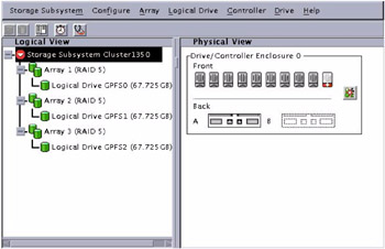
Figure 7-1: FAStT logical disk configuration
Because GPFS will distribute workloads across the disks, it is suggested that you assign the same size and the same RAID level for each logical drive.
Red Hat Linux 7.3 has QLogic driver build in it, so it will recognize the host bus adapter and external storage directly, but you might want to check the http://www.pc.ibm.com/support site for the latest firmware and driver.
To see whether your host bus adapter and FAStT Storage Server have been detected, you may browse through /var/log/messages and find messages similar to the ones highlighted in Example 7-16 or simply run the dmesg command and search the word QLogic. The dmesg command, which is used to print kernel messages, is very useful in determining if a piece of hardware has been found, and if so, what device name has been assigned.
Example 7-16: Detect the hardware
scsi2 : QLogic QLA2200 PCI to Fibre Channel Host Adapter: bus 2 device 4 irq 22 Firmware version: 2.01.35, Driver version 5.31.RH1 Vendor: IBM Model: 3542 Rev: 0401 Type: Direct-Access ANSI SCSI revision: 03 Vendor: IBM Model: 3542 Rev: 0401 Type: Direct-Access ANSI SCSI revision: 03 Vendor: IBM Model: 3542 Rev: 0401 Type: Direct-Access ANSI SCSI revision: 03 scsi(2:0:0:0): Enabled tagged queuing, queue depth 16. scsi(2:0:0:1): Enabled tagged queuing, queue depth 16. scsi(2:0:0:2): Enabled tagged queuing, queue depth 16. Attached scsi disk sdd at scsi2, channel 0, id 0, lun 0 Attached scsi disk sde at scsi2, channel 0, id 0, lun 1 Attached scsi disk sdf at scsi2, channel 0, id 0, lun 2 SCSI device sdd: 142028800 512-byte hdwr sectors (72719 MB) sdd: unknown partition table SCSI device sde: 142028800 512-byte hdwr sectors (72719 MB) sde: unknown partition table SCSI device sdf: 142028800 512-byte hdwr sectors (72719 MB) sdf: unknown partition table
The machine type of the IBM TotalStorage FAStT200 is Model 3542. Example 7-16 shows that the IBM TotalStorage FAStT200 in our ITSO lab, which is attached to the QLogic QLA2200 Fibre Channel Host Adapter, is detected as scsi2. In addition to that, the example shows that the three logical drivers created using the IBM FAStT Storage Manager are recognized as sdd, sde, and sdf, respectively. In addition to that, you should notice that there is a message unknown partition table beside each device. It is because we have not create a partition to the disk yet. You need to create partition for each disk before starting to use them as your GPFS storage.
In order to create a partition on those devices, you may use the fdisk command to create, for example, partitions on the devices /dev/sdd, /dev/sde, and /dev/sdf respectively, as follows:
# fdisk /dev/sdd # fdisk /dev/sde # fdisk /dev/sdf
The fdisk command will prompt for the type of partition (type n for new partition then p for creating a primary partition), the partition number (ranging from 1 to 4 in our example), the value of the first cylinder, and the value for the last cylinder (in our example, we accepted the default values). It also prompts you to accept the changes (pressing w to apply the changes and q to quit). Consult the official Red Hat Linux product documentation manual for a detailed explanation on how to create a partition using the fdisk command.
You can also use the fdisk command to verify that the partitions were created and display their attributes. Example 7-17 shows the fdisk command output in our ITSO lab environment. The /dev/sdd device now holds a partition named sdd1, /dev/sde holds the partition /dev/sde1, and dev/sdf holds the partition /dev/sdf1. Note that we run the fdisk command on the storage node from the management node using the ssh command.
Example 7-17: fdisk -l command output
[root@masternode bin]# ssh -n storage001 fdisk -l Disk /dev/sda: 255 heads, 63 sectors, 2212 cylinders Units = cylinders of 16065 * 512 bytes Device Boot Start End Blocks Id System /dev/sda1 * 1 6 48163+ 83 Linux /dev/sda2 7 267 2096482+ 83 Linux /dev/sda3 268 398 1052257+ 83 Linux /dev/sda4 399 2212 14570955 5 Extended /dev/sda5 399 529 1052226 82 Linux swap /dev/sda6 530 660 1052226 83 Linux /dev/sda7 661 725 522081 83 Linux Disk /dev/sdb: 255 heads, 63 sectors, 2212 cylinders Units = cylinders of 16065 * 512 bytes Device Boot Start End Blocks Id System Disk /dev/sdc: 255 heads, 63 sectors, 2212 cylinders Units = cylinders of 16065 * 512 bytes Device Boot Start End Blocks Id System Disk /dev/sdd: 255 heads, 63 sectors, 8840 cylinders Units = cylinders of 16065 * 512 bytes Device Boot Start End Blocks Id System /dev/sdd1 1 8840 71007268+ 83 Linux Disk /dev/sde: 255 heads, 63 sectors, 8840 cylinders Units = cylinders of 16065 * 512 bytes Device Boot Start End Blocks Id System /dev/sde1 1 8840 71007268+ 83 Linux Disk /dev/sdf: 255 heads, 63 sectors, 8840 cylinders Units = cylinders of 16065 * 512 bytes Device Boot Start End Blocks Id System /dev/sdf1 1 8840 71007268+ 83 Linux [root@masternode bin]#
7.3.8 Setting PATH for the GPFS command
To ease the GPFS installation, we suggest you add a path to the GPFS binary directory to your $PATH environment in all nodes. This is how we do it:
-
Create /cfmroot/etc/profile.d/mmfs.sh, which contains:
PATH=$PATH:/usr/lpp/mmfs/bin MANPATH=$MANPATH:/usr/lpp/mmfs/man
-
Run # chmod 755 /cfmroot/etc/profile.d/mmfs.sh.
-
Run # cfmupdatenode -a.
This way, the cfmupdatenode command will distribute /etc/profile.d/mmfs.sh to all nodes, including its attributes.
|
| < Day Day Up > |
|
EAN: 2147483647
Pages: 123