The Core Model
The Core Model
Understanding the Core Model is a crucial part of building your own extension schema ”unless you start with a blank sheet of paper and discard the available models in favour of "rolling your own," your components will be added somewhere beneath the Core Model. Getting your components correctly positioned is not trivial and may be difficult to adjust later.
The DMTF publishes a white paper, DSP0111, describing the Core Model that makes very useful reading.
Almost every class in CIM ultimately is a CIM_ManagedElement or, to put it another way, CIM_ManagedElement is an abstract superclass of every other CIM class (the principal exception being associations). CIM_ManagedElement provides three very general properties: Caption (a one-line description of the object), Description (a fuller textual description of the object) and ElementName (a simple name for the object).
Figure 6.1 illustrates a few of CIM_ManagedElement's subclasses which I discuss in the subsections below.
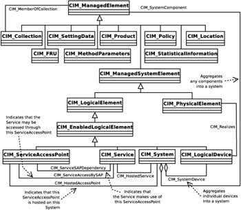
Figure 6.1: Part of the Core Model
CIM_ManagedSystemElement
This is the superclass of the great Physical/Logical split, its subclasses being CIM_PhysicalElement and CIM_LogicalElement.
You can consider every managed component of a system, whether software or hardware, to be a CIM_ManagedSystemElement. Thus, software modules, cards, integrated circuits, racks, frames , etc. are all CIM_ManagedSystemElements. The class defines properties for the date and time at which the element was installed, a name for the element and the element's state (Unknown, OK, Degraded, Stressed, Stopped, Dormant, etc.).
Note that, as defined in CIM_ManagedSystemElement, the Name property is not a key (i.e., cannot be used to identify a particular instance). It is anticipated, however, that you will derive subclasses from CIM_ManagedSystemElement (or, better, from one of its subclasses) and introduce the key property at a lower level.
CIM_ManagedSystemElement's Logical Sub-Tree
CIM_LogicalElement, the head of the logical tree beneath CIM_ManagedSystemElement, is very abstract and provides no new properties but, as seen in Figure 6.1, it acts as a superclass for two very important concepts, Systems and Services:
-
A System is a collection of elements working together to provide a particular functionality. Although the class CIM_System is defined in the core model, it is sufficiently important to be a common model in its own right. I describe it starting on page 99.
-
A Service, in the CIM sense, is a "function" of some sort which the device offers. Examples of a service might be voice mail and call forwarding on a PBX; a route calculation, source routing or forwarding in an IP router or user authentication, or printing on a computer. To determine the Services provided by a device, put yourself in the position of a user and ask yourself the question, "What does this device actually provide? Why would I want one?" The answer would not typically be "it provides a 10-GB disk drive and a POSIX API." More likely the end user would say, "it handles my voice mail and word processing." The Services then are voice mail and word processing.
In order for a Service to be used, it needs at least one point through which it may be accessed: a Service Access Point. In order for the voice mail Service to be useful, it must provide a "way in" using, say, a telephone touchpad and display which I may or may not be authorised to use. I may also be able to access my voice mail from my computer ”the Service then needs to model a further Service Access Point. Obviously CIM_ServiceAccessPoints need to be connected with their CIM_Service and this is achieved through the use of an association: CIM_ServiceAccessBySAP as shown in Figure 6.1.
Remember that CIM is concerned not with the implementation of an entity but with its management. For example, CIM describes neither how a voice mail service is implemented nor how the service is accessed (the Application Program Interface, API). Instead it models the function provided by the service (using the class CIM_Service) and the way it may be accessed (using the class CIM_ServiceAccessPoint).
So, my voice mail could be modelled as a CIM_Service and the different methods by which I may access it could be modelled as CIM_ServiceAccessPoints connected to the CIM_Service by means of associations. An operator using a WBEM client could then provision the voice mail service and enable or disable my access to it.
Note also that the voice mail service is not modelled as the computer which actually holds and distributes the voice mail or its associated software. The computer and software may well be CIM_LogicalDevices and these are managed independently of the service.
Having described a particular CIM_Service, it is essential to be able to link the service to the CIM_System which hosts it. This is done by using the CIM_HostedService association.
CIM_ManagedSystemElement's Physical Sub-Tree
CIM_PhysicalElement, the head of the physical tree, provides a large collection of additional properties including a tag (acting as a key), manufacturer, model number, stock-keeping code, serial number, version, part number, and date of manufacture.
You may be surprised to see a key this high in the class hierarchy and wonder why the physical element is not identified by reference to the device in which it is fitted. The tag (which is just a string and may contain an asset number or similar identifier) is in this position because of the potential mobility of a physical element. In general, a physical element (e.g., a card or removable disk) may be removed from a particular shelf or computer and be stored in a repair shop for some time before being inserted into a totally different system. Because a physical element has an independent existence, irrespective of the system into which it is fitted, it is given a unique key to allow it to be tracked as it moves about.
Because management protocols such as SNMP are primarily interested in the management of physical devices, it is not surprising that many of the properties of CIM_PhysicalElement map to SNMP MIB variables . PartNumber, for example, maps to MIB.IETF ”Entity-MIB.entPhysicalModelName.
CIM_Product
If you are producing a model of a new product, it is possible that you will latch onto the CIM_Product as a means of defining your new product. While this is a possible use for CIM_Product, the class is more normally used to describe a complete bought-in product. Before subclassing from CIM_Product, ask yourself: "Did I purchase this entity as a single product, does it have a serial number, is there a legal agreement between me and the vendor who produced this product and do I have a support agreement for it?"
Unless the answers are generally "yes," then what you have may not be a product in CIM terms. A CIM_Product has properties such as a serial number, vendor's name, version number and warranty dates.
CIM_FRU
Informally, you can think of a field- replaceable unit (FRU) as the thing which a maintenance technician carries on her bicycle when going into the field to repair a fault. It may be a board containing processors, ports, memory, etc. It may be a power supply unit. Whatever it is, it can be unplugged and replaced .
Because it is a replaceable unit, the CIM definition of a CIM_FRU includes an identifying number (serial number, die number, etc.), the name of the supplier, a description of the FRU and a Boolean to indicate whether the customer is allowed to replace the unit or not.
From the modelling point of view, an FRU is a collection of physical elements, products and software features. Although this may seem to be a very computer-oriented view of an FRU, reflecting the history of the DMTF, it is a useful abstraction for most FRUs.
CIM_SettingData
Typically the state of a device is represented by two values: the state in which you, the operator, want it to be and the state in which it actually is. You may, for example, have configured a slot on router 32 on site X to contain a Gigabit Ethernet interface card (required state) but the field technician may have incorrectly inserted a 80-Baud Telex card (actual state).
The purpose of keeping both the required and actual state in this way is useful in preventing misleading information being given to an operator. Consider a configuration command which takes some time to complete: change the speed of a supertanker, for example. Assuming that the tanker is travelling at 20 knots, an operator might want to change the speed to 10 knots. If the desired and actual states were not separate then, while the tanker is slowing down, a period I imagine of some minutes, an operator could not tell what was actually happening. With two distinct values for the required and actual states, the operator would see (20,10), (19,10), (18,10), and finally (10,10) as the pairs of values.
Although both the required and the current states may be represented as properties on the instance of the managed element, it is also sometimes convenient to have the required state in a different class, associated with the managed element. This is the purpose of CIM_SettingData. This class was introduced in version 2.7 of the CIM core model to replace a rather idiosyncratic class known as CIM_Setting. CIM_Setting is not recommended for new designs, so I will not describe it here.
The purpose of an instance of CIM_SettingData is to hold a group of related and relatively static parameter values. For example, the values which define a computer monitor (vertical and horizontal refresh rates, horizontal resolution, interlaced or noninterlaced scan mode, etc.) would make good candidates to be drawn together in an instance of CIM_SettingData. They are clearly related because the whole group needs to be defined to make a monitor work and they are changed relatively infrequently. A counter which changes frequently would not be a suitable candidate for CIM_SettingData.
The association CIM_ElementSettingData between the CIM_SettingData class and a CIM_ManagedElement is illustrated in Figure 6.2.
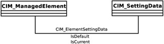
Figure 6.2: CIM_SettingData and CIM_ManagedElement
CIM_SettingData itself has only two properties: an InstanceID and an ElementName. The InstanceID is particularly complex as it needs to be unique within a namespace; I discuss the format of this property starting on page 195.
CIM_Collection
A CIM_Collection, as its name implies, allows items to be grouped in some way. A straightforward example of this appears in the DMTF's User Model (see page 114). A user, typically a human being, can usefully be modelled as being a member of various groups: his or her department, the group of people carrying out the same role, etc. As illustrated in Figure 6.10 on page 115, these groups are modelled as CIM_Collections.
Of course, once a Collection class has been defined, you need a way of saying what items are members of it. This is achieved by using the CIM_MemberOfCollection association which, as you can see from Figure 6.1, allows any CIM_ManagedElement (i.e., anything!) to be associated with a CIM_Collection.
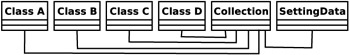
Collections are powerful when you want to associate something, not with instances of individual classes, but with instances of many classes. An example might be CIM_SettingData which is associated with classes A, B, C and D. When building the model without the concept of a Collection, you would have to build instances of associations between the SettingData and A, between the SettingData and B, etc., resulting in an explosion in the number of instances. This technique would also hide the fact that, in having the same SettingData, the four classes are actually related.
It would be better to create a collection, inheriting, perhaps indirectly, from CIM_Collection and drawing A, B, C, and D together. The collection could then represent whatever it is that they have in common and share the SettingData. The SettingData would then be associated with the Collection:
I give another example in Chapter 9 where I work through designing the model for a small device. Figure 9.9 on page 183, in particular, illustrates the collection hierarchy and an association created to link a trunk port with a number of telephony ports.
CIM_Location
Physical devices are assumed to have a particular location in space and, for many management purposes, the location is important. Rather than make the location a Property of a class such as CIM_PhysicalElement, the core model defines a CIM_Location class and an association, CIM_PhysicalElementLocation, to link a Physical Element with a Location. This reduces the amount of duplication (and the resulting difficulties in updating) if several Physical Elements are in one location.
Effectively, as you would expect, the CIM_Location class just defines an address. Its properties are:
-
Name: A string which acts as a key and defines the location.
-
PhysicalPosition: Another string which somehow defines the location. This could contain the latitude and longitude, or the site, building, rack, and slot number, depending on your application.
-
Address: Yet another string designed to contain a street address.
CIM_StatisticalInformation and CIM_StatisticalData
Most devices create statistics, perhaps counts of calls or packets for billing purposes, perhaps information about packet queue lengths or module failure rate for debugging or performance management purposes. The CIM_StatisticalInformation and CIM_StatisticalData classes are designed to hold this type of information. Of the two, CIM_StatisticalData is the younger , being introduced in version 2.7 of the model, and although CIM_StatisticalInformation is not officially deprecated, I would recommend using CIM_StatisticalData.
A possible question, of course, is why classes such as these are necessary. Because the statistics in question will relate to a particular Managed Element, why should the counters, etc., not be made properties of those Managed Elements? The answer lies to some extent in the nature of statistical counters ”they are typically dynamic and have to be fetched from devices when required and often require some form of computation to manipulate them before they are ready to be displayed to an operator. If they were properties of the Managed Element, then every time an operator totally uninterested in statistics requested information about an instance of a Managed Element, those values would have to be retrieved and calculated, placing a possibly heavy burden on the system.
So, instead of including the statistics as properties on the Managed Element, an instance of CIM_StatisticalData is created and linked to a particular CIM_ManagedElement by means of the CIM_ElementStatisticalData association. The full mof definition of this association is given in Figure 6.3 as it neatly illustrates the use of the Max and Min qualifiers described on page 72.
| |
[Association, Version ("2.7.0"), Description ( "CIM_ElementStatisticalData is an association that relates " "a ManagedElement to its StatisticalData. Note that the " "cardinality of the ManagedElement reference is Min(1), " "Max(1). This cardinality mandates the instantiation of " "the ElementStatisticalData association for the " "referenced instance of CIM_StatisticalData. " "ElementStatisticalData describes the existence " "requirements and context for the CIM_StatisticalData, " "relative to a specific ManagedElement.") ] class CIM_ElementStatisticalData { [Key, Min(1), Max(1), Description ( "The ManagedElement for which statistical or metric " "data is defined.") ] CIM_ManagedElement REF ManagedElement; [Key, Description ( "The statistic information/object.") ] CIM_StatisticalData REF Stats; }; | |
Figure 6.3: The CIM_ElementStatisticalData Association
A good example of the use of CIM_StatisticalData is described in the paper "Generic On-Line Discovery Of Quantitative Models For Service Level Management" by Diao et al. of the IBM T.J. Watson Research Center, presented at the 2003 IEEE Conference on Integrated Management. This team was interested not in CIM per se, but in determining which of the 500 or so metrics available from their database system were actually significant in estimating management performance. The team, therefore, was a user rather than a designer of a CIM management system and their use of the information collected in CIM_StatisticalData instances illuminates a user's perspective.
The CIM_StatisticalData class itself defines a number of properties, including:
-
An InstanceID which must be unique within the namespace. As for the CIM_SettingData class, see my description on page 195.
-
An ElementName which is a user-friendly name for the instance.
-
A method which can be invoked to reset one or more of the counters contained in the statistical data.
EAN: N/A
Pages: 152