Refining All Foreign Keys
Establishing Each Relationship
This process involves defining an explicit logical connection between a pair of related tables. The type of relationship that exists between the tables determines the manner in which you define the connection.
One-to-One and One-to-Many Relationships
You use a primary key and a foreign key to establish the connection between tables participating in a one-to-one or one-to-many relationship. (You'll learn the definition of a foreign key in just a moment.)
The One-to-One Relationship
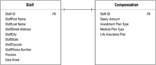
In this type of relationship, one table serves as a parent table and the other serves as a child table. A record must exist in the parent table before you can enter a related record in the child table; stated another way, a record in the child table must have a related record in the parent table. The roles you assign to the tables usually depend on the subjects they represent, although there will be instances when you can assign the roles rather arbitrarily. In Figure 10.32, for example, you would most likely assign the parent role to the STAFF table and the child role to the COMPENSATION table. This is a reasonable assumption because it would be completely illogical to have a record in the COMPENSATION table that is not related to a record in the STAFF table.
Figure 10.32. Which table would you pick as the parent table?
In the case where one of the tables is a subset table, you will usually assign the child role to the subset table. There are instances, however, when you can assign the parent role to the subset table.
You establish a one-to-one relationship by taking a copy of the parent table's primary key and incorporating it within the structure of the child table, where it then becomes a foreign key . (The term foreign key is derived from the fact that the child table already has a primary key of its own, and the primary key you are introducing from the parent table is "foreign" to the child table.) In most one-to-one relationships, however, the foreign key also serves as the child table's primary key.
Figure 10.33 illustrates how you would establish the relationship between the STAFF and FACULTY tables. STAFF is the parent table in this case because a record in the FACULTY table must be related to a record in the STAFF table; faculty members are drawn from the school's staff. If you were to follow the procedure you just learned, you would take a copy of the STAFF table's primary key and incorporate it as a foreign key in the FACULTY table. This is unnecessary, however, because FACULTY is already a properly defined subset table. (Recall that a subset table and the data table from which it was derived must share the same primary key. You learned how to define a subset table in Chapter 7 and how to establish its primary key in Chapter 8.)
Figure 10.33. Establishing the one-to-one relationship between the STAFF and FACULTY tables.
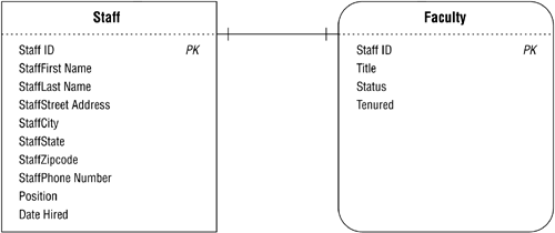
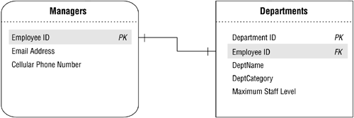
Figure 10.34 shows a slightly different example of a one-to-one relationship. Assume that MANAGERS is a subset table of EMPLOYEES, but has a direct relationship to DEPARTMENTSa single manager is associated with only one department, and a single department is associated with only one manager. Further assume that MANAGERS is the parent table and DEPARTMENTS is the child table. (This is a good example of a scenario in which you can choose the roles rather arbitrarily. It's also an instance of when a subset table plays the parent role within the relationship.)
Figure 10.34. A one-to-one relationship with a subset table in the parent role.

Establish the relationship between these tables using the procedure you've just learned, and then identify the DEPARTMENTS table's new foreign key (E MPLOYEE ID) by placing the letters "FK" next to its name . Figure 10.35 shows the revised relationship diagram with the results of your modifications.
Figure 10.35. Establishing the relationship between the MANAGERS and DEPARTMENTS tables.
As long as you can visualize this process generically, you'll be able to establish any one-to-one relationship you encounter.
Note
Many database designers will use M ANAGER ID as the primary key name in the MANAGERS table and the foreign key name in the DEPARTMENTS table. I choose to use E MPLOYEE ID instead for these reasons:
-
MANAGERS is a subset of the EMPLOYEES table, so it shares the same primary key (E MPLOYEE ID).
-
It keeps the field in conformance with the Elements of the Ideal Field. ( It retains a majority of its characteristics when it appears in more than one table. )
-
It keeps the field in conformance with the Elements of a Foreign Key. (You'll learn about foreign keys later in this chapter.)
-
It removes any possible ambiguity or doubt about the true nature of a foreign key. (I'll explain this in more detail during the discussion of the Elements of a Foreign Key.)
There is no absolute right or wrong way to do thisin the end, the approach you use is simply a matter of style. Once you decide which approach you want to use, however, make certain you use it consistently.
There is a small change in the way you'll diagram the relationships from this point forward. You should now use the primary key as the beginning point and the foreign key as the end point of the relationship line. (The only exception will be when you're diagramming the relationship between a subset table and its parent data table.) Making this minor modification will help you visualize the relationships more clearly and make it easier to identify the fields that establish the relationship.
The One-to-Many Relationship
The technique you use to establish a one-to-many relationship is similar to the one you used to establish a one-to-one relationship. You simply take a copy of the primary key from the table on the "one" side of the relationship and incorporate it within the table structure on the "many" side, where it then becomes a foreign key. For example, consider the one-to-many relationship between the BUILDINGS and ROOMS tables shown in Figure 10.36.
Figure 10.36. The existing one-to-many relationship between the BUILDINGS and ROOMS tables.

The relationship between these two tables is such that a single building can contain one or more rooms, but a single room is contained within only one building. Using the procedure above, you establish this relationship by taking a copy of the primary key (B UILDING N UMBER ) from the BUILDINGS table and incorporating it as a foreign key within the ROOMS table. Now, revise the relationship diagram and make the same type of adjustments as you did with the diagram for the one-to-one relationship. Your revised diagram should look like the one in Figure 10.37. (Note that the middle line of the crow's foot symbol is the significant connection pointit should point directly to the foreign key.)
Figure 10.37. Establishing the one-to-many relationship between the BUILDINGS and ROOMS tables.

Resolving Multivalued FieldsRevisited
Back in Chapter 7 you learned how to resolve a multivalued field by using this generic procedure:
-
Remove the field from the table and use it as the basis for a new table. If necessary, rename the field in accordance with the field naming guidelines that you learned earlier in this chapter.
-
Use a field (or set of fields) from the original table to relate the original table to the new table; try to select fields that represent the subject of the table as closely as possible. The field(s) you choose will appear in both tables.
-
Assign an appropriate name, type, and description to the new table and add it to the final table list.
You used this procedure to resolve a multivalued field called C ATEGORIES T AUGHT in an INSTRUCTORS table. Figure 10.38 shows the original version of the table and the results of applying the procedure.
Figure 10.38. The original resolution of the C ATEGORIES T AUGHT multivalued field.
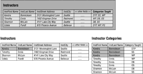
There's one final fact about a multivalued field that you need to learn: An inherent one-to-many relationship exists between a given set of values within a multivalued field and the record in which they reside. You'll see this when you examine the original INSTRUCTORS table in Figure 10.38. A single instructor (such as Kendra Bonnicksen) can teach one or more categories (DTP, SS, WP)this holds true for every record in the table.
When you properly resolve the multivalued field, the tables produced by the procedure inherit the relationship. This is clearly the case with the revised INSTRUCTORS and new INSTRUCTOR CATEGORIES tables. You can now establish this one-to-many relationship as you would any other. (Of course, this assumes that you've assigned a primary key to the INSTRUCTORS table.) Figure 10.39 shows the results of properly establishing this relationship.
Figure 10.39. Establishing the one-to-many relationship between the INSTRUCTORS and INSTRUCTOR CATEGORIES tables.

The I NSTRUCTOR ID field in the INSTRUCTOR CATEGORIES table serves as a foreign key and helps to establish the one-to-many relationship between the INSTRUCTORS and INSTRUCTOR CATEGORIES tables. I NSTRUCTOR ID is also part of the composite primary key for the INSTRUCTOR CATEGORIES table; a given combination of I NSTRUCTOR ID and C ATEGORY T AUGHT values uniquely identifies a specific record in the table.
The Many-to-Many Relationship
You establish a many-to-many relationship with a linking table. This is a new table that you'll create using the following three-step procedure.
-
Define the linking table by taking copies of the primary key from each table in the relationship and using those keys to form the structure of the table. These fields will serve two distinct purposes within the linking table: Together they constitute the table's composite primary key , and each is a unique foreign key that helps to establish a relationship between its parent table and the linking table.
-
Give the linking table a name that represents the nature of the relationship between the two tables. For example, if you're establishing a many-to-many relationship between a PILOTS table and a CERTIFICATIONS table, you might choose to call the linking table PILOT CERTIFICATIONS.
-
Add the linking table to the final table list and make the proper entries for "Table Type" and "Table Description."
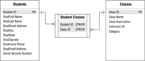
Figure 10.40 shows how you establish the many-to-many relationship between the STUDENTS and CLASSES tables. (Note the new diagram symbol used to represent a linking table.)
Figure 10.40. Establishing the many-to-many relationship between the STUDENTS and CLASSES tables.
Note
You could have used STUDENT SCHEDULES or CLASS SCHEDULES as the name of the linking table; STUDENT CLASSES just happens to be my personal preference. The point to remember is that you should use a name that makes the most sense to you or to the organization.
Creating a linking table produces a few noteworthy results.
-
The original many-to-many relationship has been dissolved because there is no longer a direct relationship between the STUDENTS and CLASSES tables. The original relationship has been replaced by two one-to-many relationships: one between STUDENTS and STUDENT CLASSES and another between CLASSES and STUDENT CLASSES. In the first relationship, a single record in STUDENTS can be associated with one or more records in STUDENT CLASSES, but a single record in STUDENT CLASSES table can be associated with only one record in STUDENTS. In the second relationship, a single record in the CLASSES table can be associated with one or more records in STUDENT CLASSES, but a single record in STUDENT CLASSES can be associated with only one record in CLASSES.
-
The STUDENT CLASSES linking table contains two foreign keys. S TUDENT ID and C LASS ID are both copies of the primary keys from the STUDENTS and CLASSES tables respectively; therefore, each is a foreign key by definition. As such, they help to establish the relationship between their parent tables and the linking table.
-
The STUDENT CLASSES linking table has a composite primary key composed of the S TUDENT ID and C LASS ID fields. Except in rare instances, a linking table always contains a composite primary key. (This rule applies to the database's logical design only. There are various reasons why you might break this rule when you transform the logical design into a physical design, but this is a discussion that is beyond the scope of this book.) It's important to note that you'll occasionally have to add more fields to the linking table in order to guarantee a unique primary key value. For example, assume the school decides to record student schedules for every term of the school year (fall, winter, and spring). You would have to add a new field, perhaps called T ERM , and designate it as part of the composite primary key. This would enable you to enter another instance of a given student and class into the table, but for a different term; a student may need to retake a class during the spring term because he failed the class in the fall term.
-
The linking table helps to keep redundant data to an absolute minimum. There is no superfluous data in this table at all. In fact, the main advantage of this table structure is that it allows you to enter as few or as many classes for a single student as is necessary. Later in the database-design process, you'll learn how to create views to draw the data from these tables together in order to present it as meaningful information.
-
The name of the linking table reflects the purpose of the relationship it helps establish. The data stored in the STUDENT CLASSES table represents a student and the classes in which he or she is enrolled.
As you work with many-to-many relationships, there will be instances in which you will need to add fields to the linking table in order to reduce data redundancy and further refine structures of the tables participating in the relationship. For example, assume you're working on a new database with a colleague and he's just brought the ORDERS and PRODUCTS tables in Figure 10.41 to your attention.
Figure 10.41. Is there a problem with either of these tables?
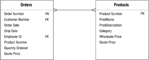
You note that there's a many-to-many relationship between the tables and then realize that your colleague tried to establish this relationship by taking a copy of the P RODUCT N UMBER and Q UOTE P RICE fields from the PRODUCTS table and incorporating them into the ORDERS table. He thought that this was the best way to associate various products with a particular order. The presence of these fields in the ORDERS table, however, produces a large amount of redundant data. Figure 10.42 illustrates this problem quite clearly.
Figure 10.42. Redundant data caused by an improperly established many-to-many relationship.

You can enter only one product number, quantity ordered, and quote price for any given record; therefore, you'll have to enter a new record into the table for each item a customer places on his order. Customer number 9001, for example, included eight items on an order he made on May 16, so there are eight records in the table for this order alone.
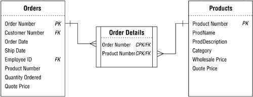
Based on what you've learned earlier in this chapter, you know that this is an improper way to establish this relationship. You also know that you can establish the relationship properly by creating and using a linking table. So you remove the P RODUCT N UMBER field from the ORDERS table, establish the relationship in the appropriate manner, and revise the relationship diagram. Figure 10.43 shows the results of your work.
Figure 10.43. Properly establishing the many-to-many relationship between the ORDERS and PRODUCTS tables.
You've eliminated the redundant data in the ORDERS table, but you still have two minor problems.
-
The Q UOTE P RICE and Q UANTITY O RDERED fields are no longer appropriate for the ORDERS table; the ORDERS table's primary key does not exclusively identify their values, and they bear no relationship to any of the remaining fields in the table. They do, however, relate to a particular P RODUCT N UMBER that's part of a given order within the ORDER DETAILS table.
-
You have duplicate data because there are two copies of the Q UOTE P RICE field: one in the ORDERS table and another in the PRODUCTS table.
So you resolve the first problem by removing the Q UOTE P RICE and Q UANTITY O RDERED fields from the ORDERS table and incorporating them within the ORDER DETAILS table. You then resolve the second problem by deleting the Q UOTE P RICE field from the PRODUCTS table; it makes more sense to associate a quote price with a product as it's being ordered. Finally, you modify the relationship diagram to reflect the changes you made to the structures. Figure 10.44 shows your revised diagram.
Figure 10.44. The revised ORDER DETAILS linking table.
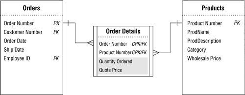
When you establish a many-to-many relationship between a pair of tables, make certain you check each table and determine whether there are any fields that you should transfer to the linking table. When in doubt, load all the tables with sample data; this will usually reveal any potential problems.
Note
You won't encounter this problem very often if you faithfully follow the design process you've learned thus far. It will typically arise, however, when you're trying to incorporate a pair of tables from an existing or legacy database and you haven't taken the time to refine their structures properly. You'll also encounter this problem when you work with someone who has little or no database-design experience.
Self-Referencing Relationships
Establishing a self-referencing relationship will be a relatively simple task now that you know how to establish a relationship between a pair of tables.
One-to-One and One-to-Many
You use a primary key and a foreign key to establish these self-referencing relationships, just as you do with their dual-table counterparts. The difference here, however, is that the foreign key will reside in the same table as the primary key to which it refers. You'll often find that the foreign key is already part of the table's structure. If the foreign key does not already exist, you'll simply create one.
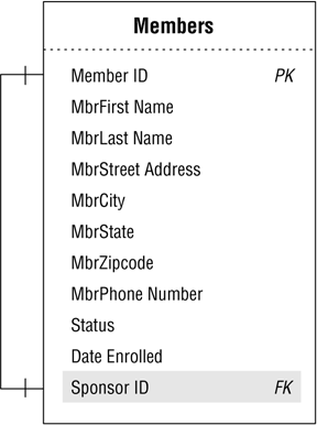
Let's revisit the MEMBERS table example from Figure 10.20. Recall that this table has a self-referencing one-to-one relationship because a given member can sponsor only one other member within the organization; the S PONSOR ID field stores the member identification number of the member acting as a sponsor. Because the S PONSOR ID field draws its values exclusively from the M EMBER ID field, it acts as the foreign key for the relationship. You establish the relationship by officially designating the S PONSOR ID field as the foreign key and notating it as such in the relationship diagram. Figure 10.45 shows the revised relationship diagram for the MEMBERS table.
Figure 10.45. Establishing the self-referencing one-to-one relationship for the MEMBERS table.
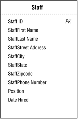
Now, consider the STAFF table example in Figure 10.46. You may remember that this table has a self-referencing one-to-many relationship because a single staff member can manage one or more other staff members.
Figure 10.46. The current structure of the STAFF table.
There is currently no means of associating a given staff member to other staff members within the table; therefore, you must create a new field that will act as the foreign key and enable you to establish the relationship. Let's assume you create a new foreign key field called M ANAGER ID that will draw its values exclusively from the S TAFF ID field. You now establish the relationship by officially designating M ANAGER ID as the foreign key and notating it as such in the relationship diagram. Figure 10.47 shows the revised relationship diagram for the STAFF table.
Figure 10.47. The revised STAFF table with the new M ANAGER ID foreign key.
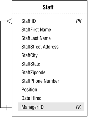
You probably noticed that the "one" side of the relationship line points to the M ANAGER ID field and the "many" side of the line points to the S TAFF ID field. This is perfectly acceptable because a manager will manage one or more staff members, but a given staff member reports to only one manager. (As you may have intuitively guessed, the "one" side of the line commonly points to the primary key and the "many" side to the foreign key.)
As you work with self-referencing one-to-one and one-to-many relationships, take a moment and examine each table's structure carefully . You'll occasionally find that you can (or may need to) modify and improve the existing structure in order to eliminate the relationship. I know what you're wondering: "But why would I want to do that?"
Retrieving information from tables with these types of relationships can be tedious and somewhat difficult. (A discussion of the reasons for this is, unfortunately , outside the scope of this work.) Additionally, the very presence of the relationship can indicate the need for new field and table structures.
Consider the STAFF table once again. Does it occur to you that if there is a need to track staff members who are managers, there could be a need to track the departments they manage? If this is true, then there must be other facets of the departments that you need to track in the database. You should now conduct a quick interview with the appropriate staff members to answer these questions and then take the appropriate action based on their responses.
Let's assume you were right and the organization does want to track departmental data. Figure 10.48 shows one possible approach you might use to accomplish this task.
Figure 10.48. Results of eliminating the self-referencing relationship and adding new structures to track departmental data.
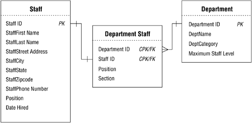
These new structures and relationships enable you to track the data efficiently and will provide a wide variety of information about the departments. (You will, of course, ensure that the new fields and tables conform to the various design elements that you've learned thus far.)
It's important to note that self-referencing relationships do have their place within a well-designed database. You should be vigilant, however, and make certain that each self-referencing relationship does indeed serve a useful purpose.
The Many-to-Many Relationship
You use a linking table to establish this type of self-referencing relationship, just as you do with its dual-table counterpart . Establishing this relationship is slightly different in that the fields you use to build the linking table come from the same parent table.
Let's revisit the PARTS table example from Figure 10.24. Recall that this table has a self-referencing many-to-many relationship because a particular part can comprise several different component parts, and that part itself can be a component of other parts. You establish this relationship as you would any other many-to-many relationshipwith a linking table. There is currently no way to associate a given part to other parts within the table, so you must create a new field for this purpose. Say, for example, that you create a field called C OMPONENT ID. This field will store the part identification number of a part that serves as a component of a parent part. You can now use the P ART ID and C OMPONENT ID fields as the basis for the linking table. For the sake of our example, we'll assume that the name of the new linking table is PART COMPONENTS . Once you've created and named the linking table, be sure to revise the relationship diagram for the PARTS table. Figure 10.49 shows the results of your work.
Figure 10.49. Establishing the self-referencing many-to-many relationship for the PARTS table.
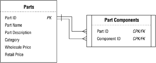
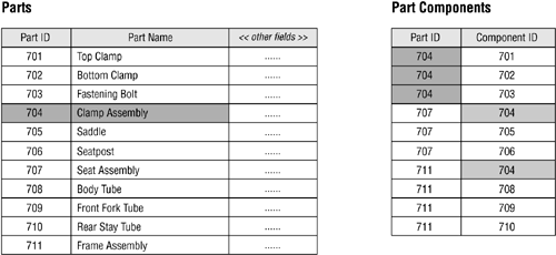
As you can see, the PARTS table now has two distinct one-to-many relationships with the PART COMPONENTS table. The first relationship is established via the P ART ID field and the second relationship is established via the C OMPONENT ID field. Figure 10.50 illustrates how these relationships work. Note that a clamp assembly (Part ID 704) contains three components and is itself a component of a seat assembly (Part ID 707) and a frame assembly (Part ID 711).
Figure 10.50. Data relationships between the PARTS and PART COMPONENTS tables.
Now, use the techniques you've just learned to establish all of the relationships you've identified among the tables in the database. Make absolutely certain you create a diagram for each relationshipyou're going to add new information to these diagrams as the design process further unfolds.
Reviewing the Structure of Each Table
Review all of the table structures after you've established the relationships between tables. Remember that you made modifications to the existing table structures and created several new table structures as you established the relationships; therefore, you want to make certain that each table conforms to the Elements of the Ideal Table.
Elements of the Ideal Table
-
It represents a single subject, which can be an object or event.
-
It has a primary key.
-
It does not contain multipart or multivalued fields.
-
It does not contain calculated fields.
-
It does not contain unnecessary duplicate fields.
-
It contains only an absolute minimum amount of redundant data.
When you determine that a table does not comply with the Elements of the Ideal Table, identify the problem and make the necessary modifications. Then, take the table through the appropriate stages of the database-design process until you return to this point. You shouldn't encounter any problems with the tables if you've been following proper procedures thus far.
| |
| Top |
EAN: 2147483647
Pages: 203