Integrity Virtual Machines Example Scenario
| This Integrity Virtual Machines example scenario discusses the creation and monitoring of several VM guests within a single VM host. Table 6-1 shows the physical configuration of the VM host server. The VM host is an nPartition in an Integrity rx8620 server with four cells. The VM host is running in an nPartition that has one cell, four CPUs, and 16 Gb of memory.
Table 6-2 shows the configuration of the VM guests that will be created during this scenario. Of particular interest in the table are the storage devices. Notice that each VM guest is allocated one disk device. Furthermore, the device files for virtual devices in the VM guests are identical. This greatly simplifies the administration of the individual VMs because the I/O devices are identical for every VM guest. As a simple example, this type of configuration allows (though does not require) files such as /etc/fstab to be identical for each VM guest.
Finally, the virtual networking devices shown in Table 6-3 further emphasize the simplicity and consistency available through the use of VMs. The virtual networking device is identical in each of the VMs and they are all connected to the same virtual network switch, named intranet. Integrity Virtual Machines Scenario OverviewThe Integrity Virtual Machines example scenario discusses the following steps that are commonly performed during the initial deployment of Integrity Virtual Machines.
Preparing the VM HostInstalling the VM software is the first task when using Integrity Virtual Machines. It consists of the VM monitor, the VM application, the VM kernel driver, the VM WBEM Provider, the VM command-line interfaces, and the VM management GUI, all of which can be installed from a single depot. After installing the VM software and tuning the HP-UX kernel as required, the physical disks and networking must be set up to support all of the VM guests that will be configured. As previously described, proper configuration of the VM host's networking and storage can greatly simplify the configuration of the VM guests. After installing the VM host software and configuring the hardware, the VM guests can be created. Creating a VM GuestThe next step is creating the first VM guest. The screen shown in Figure 6-4 is the initial VM host configuration. Since this is the first VM guest to be created on the VM host rex01, the initial screen of the VM management application displays information about the VM host and its capacity. From the initial screen, creating a new VM guest is one of the possible actions. Figure 6-4. Initial Virtual Machine Configuration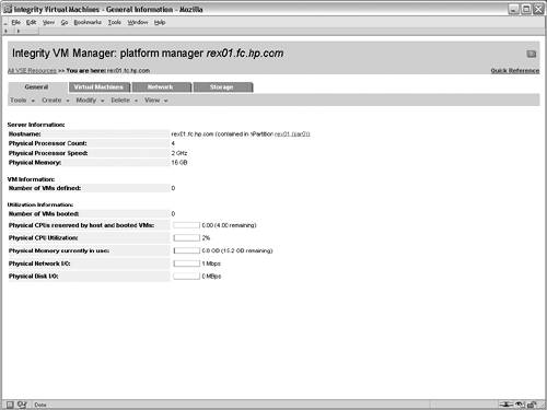 Figure 6-5 shows the initial screen of the Create VM Guest wizard. The first step consists of specifying the name of the VM guest. In this case, the rex05 VM is the first VM to be created so its name is specified in the appropriate field. When specifying the name of the VM, it's important to keep in mind all of the VM commands rely on the VM guest name as the identifier when performing management tasks. Second, a description can be used to provide a brief explanation of the VM guest's role or function. The description is used only for display purposes to help identify the VM guest. Finally, the hostname or IP address of the VM guest should be specified on this screen. This field does not set the IP address for the VM guest. Instead, this field allows management applications that are communicating with the VM host to contact the VM guests to gather additional information, including resource utilization and I/O configuration information. Figure 6-5. Identify Virtual Machine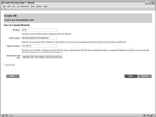 Figure 6-6 shows the next screen in the wizard, which is the processor specification screen. This page sets the number of processors and their entitlements for the VM guest. In this screen's simplest form, only the number of virtual CPUs assigned to the VM guest must be specified. If the entitlement is not explicitly configured, the VM guest will receive a minimum entitlement necessary to run an operating system and will be allowed to share resources with other VMs. Figure 6-6. Specify Virtual Machine Processor Entitlements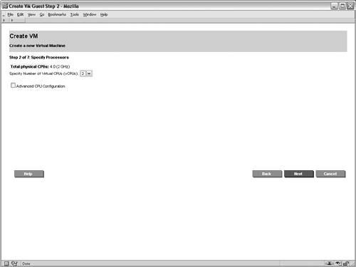 The CPU specification screen also provides an advanced mode for specifying the exact CPU entitlements. The CPU entitlement can be specified as a percentage of a physical CPU or it can be specified according to the desired clock speed of the virtual CPU. The advanced CPU configuration portion of the screen is not shown. After specifying the processors, the next step in the wizard, which is not shown, is to allocate memory to the VM guest. In this scenario, 2GB of memory is being allocated to the rex05 VM. To assist with the allocation of memory, the screen provides the amount of memory allocated to the VM host, the amount available that can be allocated to VM guests, and the amount that has already been allocated to other VM guests. Integrity Virtual Machines support VM guests with as little as 256 MB of memory, but the recommendations of the VM guest operating system should be consulted. For HP-UX as the VM guest operating system, HP recommends a minimum of 1GB of memory. Specifying the networking devices for the VM guest is the next step. While you are creating a VM guest, you may need to create a new virtual switch (vswitch). A vswitch is a virtual network that runs within the VM host. All of the VM guests connected to a given vswitch can communicate with one another using the vswitch and realize significant performance benefits because the network traffic never leaves the physical VM host. In addition, using vswitches allows multiple VM guests to share the same physical network interface card or APA device. When VM guests are communicating with systems outside the VM host, the network packets look as if they have been sent from physically separate systems as the hardware addresses are unique for every VM guest. When creating a virtual network switch (vswitch), the following attributes are required:
The screen for creating vswitches is not shown in this example scenario. After creating the intranet vswitch, the next step in the wizard adds a virtual network device to the VM guest that will rely on the vswitch. Figure 6-7 shows the interface for adding a net work device in the Create VM Guest wizard. In this case, the newly created intranet vswitch is selected from the list of available vswitches. Multiple network adapters can be added to a VM guest, in which case this process is repeated as necessary. However, in this scenario, each VM guest will be connected to only one network. Figure 6-7. Add Network Device to Virtual Machine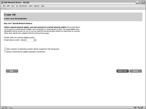 After configuring the networking devices for the VM guest, storage devices must be assigned. The interface for adding storage devices is shown in Figure 6-8. This screen allows physical and logical storage to be mapped to virtual devices in the VM guest. For this scenario, the physical disk device /dev/rdsk/c1t6d0 is being mapped to a virtual disk device for the rex05 VM. As a result of this mapping, the rex05 VM will have complete and exclusive access to the physical disk device. However, the VM will have a virtualized device path, as shown in Table 6-3. The benefit of this mapping is that the configuration within each of the VM guests can be identical, regardless of the physical storage devices that are backing the virtual storage devices. This consistency affords numerous system administration efficiencies because the management of each VM guest is repeatable and predictable. Figure 6-8. Add Disk Device to Virtual Machine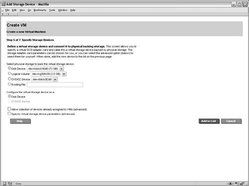 After configuring the storage devices for the VM, the administrators for the VM guest are configured. Note the administrator's screen is not shown in this example. The root user on the VM host always has full control to boot, shut down, remove, and administer all of the VM guests. However, other non-root users and groups can be configured with administrative privileges. In this scenario, only the root user will be allowed to perform administration tasks on the rex05 VM. When adding non-root administrators for a VM guest, the configured administrators are allowed to perform administrative duties only from the VM host for the allowed VM guests. These administrative privileges do not extend into the VM guest operating system. If that is required, the user or group must be granted the appropriate permissions from within the VM guest's operating system. The purpose for having non-root administrators on the VM host is to allow non-root users to perform certain administrative duties on a subset of the VM guests. At this point, the necessary steps required to create the rex05 VM guest are complete. The final screen in the wizard is a summary of the VM guest that will be created. The summary screen is not shown, but it contains the information that has been supplied for the creation of the VM guest. The processor entitlements, memory allocation, networking devices, and storage devices that have been specified for the VM guest are shown in the various tabs of the summary screen. All of the tabs on the summary screen should be carefully reviewed to ensure that the settings were input properly. In addition to the configuration options for the VM guest, one of the tabs in the summary screen shows a preview of the command that will be executed on the VM host to create the VM guest. This screen is useful to assist in learning the proper syntax and usage of the Integrity Virtual Machines command-line interfaces. Pressing the finish button on the summary screen results in the creation of the VM guest. Booting the Virtual MachineThe final step required to complete the creation of the VM guest is installing an operating system. Integrity Virtual Machines provides a simulated firmware interface shell, specifically the Extensible Firmware Interface (EFI), which is used to install an operating system either over the network or from DVD media in the same way it would be done on a physical Integrity platform. Viewing the Virtual MachineThe status and configuration of Integrity Virtual Machines can be viewed from the VM management GUI or from the VM command-line interfaces. Figure 6-9 shows the configuration for the rex05 VM guest. It displays the overall status and configuration of the VM guest as well as graphical views illustrating the mapping of physical networking and storage devices to the virtual networking and virtual storage counterparts. Figure 6-9. Virtual Machine Guest Details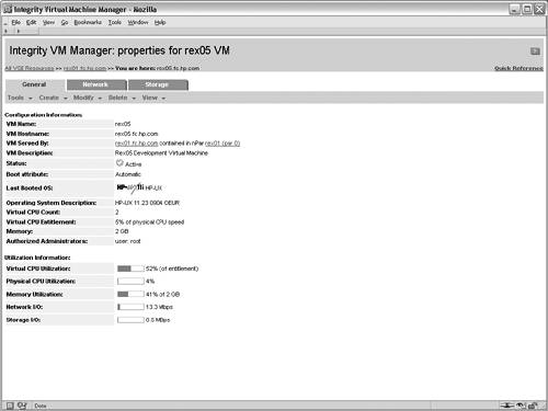 In addition to the graphical status information, the Integrity Virtual Machines command-line interface can be used to view the status of VM guests. The output shown in Listing 6-1 is the textual status and configuration of the rex05 VM. Listing 6-1. Virtual Machine Command Line Status # hpvmstatus V [Virtual Machines] Virtual Machine Name : rex05 Virtual Machine UUID : 9c39a408-60c9-11d9-84a2-000e7fed810c Virtual Machine ID : 4 Virtual Machine Label : Development VM for Web Application VM's Model Name : server Integrity Virtual Machine VM's Serial Number : VM00448001 Operating System : HPUX OS Version Number : B.11.23 State : Up Boot type : Unknown Console type : vt100-plus Number of virtual CPUs : 2 Number of devices : 1 Number of networks : 1 Memory : 1 GB At this point, additional VM guests can be created and booted. This example scenario does not walk through the steps for creating the additional VM guests. The remaining screens in this example illustrate the visualization capabilities of the VM management GUI on a VM host with several VM guests running. Viewing Integrity Virtual Machines ConfigurationThe configuration of Integrity Virtual Machines can be viewed using the command-line interface or through the VM management application. Figure 6-10 shows the high-level configuration and status of the VM guests that have been created within the rex01 VM host. Notice that the virtual CPU entitlements and the virtual CPU utilization metrics are shown in this summary view, along with memory, network I/O bandwidth, and disk I/O bandwidth utilization information. Figure 6-10. Integrity Virtual Machines Guest General Information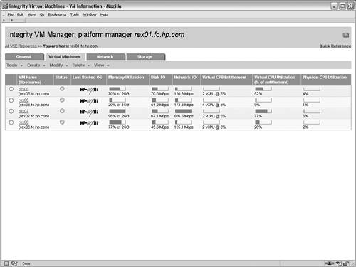 The networking view of the virtual machine management application is shown in Figure 6-11. This view graphically illustrates mapping of virtual network resources in the VM guests to the physical network devices in the VM host. This view serves as a vital resource when troubleshooting network performance issues because the utilization of each virtual network device can be visually traced back to the physical networking interface and vice versa. The network tab also makes evident which VM guests are using each of the virtual switches and which VMs have exclusive access to network devices in the VM host. Figure 6-11. Integrity Virtual Machines Guest Network Configuration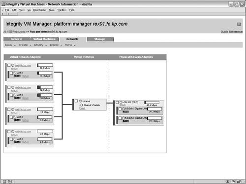 Figure 6-12 is the final graphical view in the virtual machine management application. Akin to the network tab, this tab graphically displays each virtual storage device configured for the VM guests and their associated physical devices in the VM host. This view makes it easy to make configuration decisions and troubleshoot storage issues, especially when multiple physical storage devices are connected to the VM host through the same physical storage adapter. In such a configuration, extremely high storage traffic by a VM guest could create a situation in which another VM guest experiences degraded storage performance. Figure 6-12. Integrity Virtual Machines Guest Storage Configuration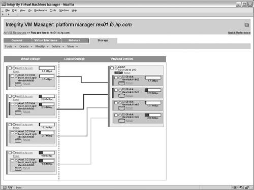 These views provide a tremendous amount of information and troubleshooting capabilities for VM guests. This level of detail is vital in an environment where physical resources are virtualized and shared between multiple operating systems. |
EAN: 2147483647
Pages: 197
- Information Security and Risk Management
- Legal, Regulations, Compliance, and Investigations
- Understanding Certification and Accreditation
- Appendix D The Information System Security Engineering Professional (ISSEP) Certification
- Appendix E The Information System Security Management Professional (ISSMP) Certification