11.1 Conventional Hub Bottlenecks
11.1 Conventional Hub Bottlenecks
This section examines why conventional hubs, which were developed to facilitate the cabling of network devices, also function as a bottleneck with respect to the use of network bandwidth. In doing so, we will discuss the operation of both Ethernet and Token Ring hubs, with the latter primarily referred to as a multistation access unit (MAU).
11.1.1 Ethernet Hub Operation
In an Ethernet environment, a single LAN is usually referred to as a segment, with large networks typically composed of multiple segments connected by a bridge or router. The early implementations of Ethernet in the form of 10BASE-5 and 10BASE-2 coaxial cable-based networks resulted in the use of a common medium to which workstations are attached. This is illustrated in Figure 11.1, which shows the cabling structure of a coaxial-based Ethernet network.
Based on the fact that the bandwidth of the media is shared with only one user able to transmit at any given time, the Ethernet LAN segment shown in Figure 11.1 is commonly referred to as a shared-media, shared-bandwidth network.
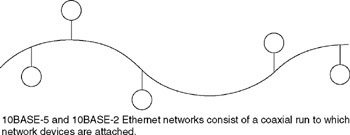
Figure 11.1: A Shared Media, Shared Bandwidth Ethernet LAN Segment
A change in the network topology and cabling structure of Ethernet resulted in the development of hub-centric 10BASE-T networks, in which cabling from individual network devices to dedicated ports on the hub resulted in a star-wiring configuration. When two or more hubs are interconnected to a common network, the wiring topology resembles a star-bus structure as illustrated in Figure 11.2. Although the wiring topology changed, the use of hubs did not alter the fact that the network remained a shared-media, shared-bandwidth network.
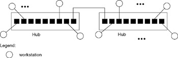
Figure 11.2: A Two-Hub 10BASE-T Ethernet Network
To illustrate the problem associated with the use of a shared-media, shared-bandwidth network, let us examine the operation of a conventional Ethernet hub. This type of hub simply duplicates nodes attached to the hub. Figure 11.3 illustrates the data flow when one workstation (node 1) transmits a frame to another workstation, file server, gateway, or another network device that is either connected to the same hub or to another hub that is connected to the hub to which the data originator is connected. Because the hub functions as a data regenerator, the frame is repeated onto each connection to the hub to include interconnections to other hubs. This restricts dataflow to one workstation at a time, because collisions occur when two or more attempts to gain access to the media happen at the same time.
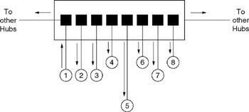
Figure 11.3: Conventional Hub Dataflow
11.1.2 Token Ring Hub Operation
Although dataflow on a Token Ring network is circular, this type of network is also a shared-media, shared-bandwidth network. In a Token Ring network environment, hubs, referred to as multistation access units (MAUs), are connected via their Ring In and Ring Out ports to form a star-ring topology similar to that shown in Figure 11.4. The actual dataflow of a frame is from one device to the next, to include flowing down the cable, called a lobe, connecting the device to the MAU port, to an attached device and back to the port prior to flowing to the next port. Because only one frame can flow on the network at any point in time, access to the bandwidth is also shared. Thus, a Token Ring network also represents a shared-media, shared-bandwidth network.
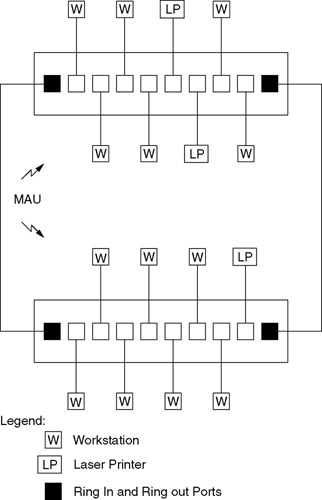
Figure 11.4: The Connection of Token Ring MAUs Forms a Star-Ring Topology
11.1.3 Bottleneck Creation
Conventional Ethernet hubs create network bottlenecks because all traffic flows through a shared backplane in the hub. Thus, each device connected to an Ethernet hub competes for a slice of the bandwidth of the backplane. In a Token Ring environment, devices compete to acquire a token, resulting in the sharing of network bandwidth in a similar manner. The end result of this bandwidth sharing is an average transmission rate per device that is many times below the operating rate of the network. For example, consider a departmental 10BASE-T network operating at 10 Mbps and consisting of 12 interconnected eight-port hubs that supports a total of 96 devices. Then, the average slice of bandwidth available for each device is 10 Mbps/96, or approximately 104 Kbps. Note that although each device transmits and receives data at the LAN operating rate of 10 Mbps, their average data transfer capability is approximately 104 Kbps because each device must compete with 95 other devices to obtain access to the network. Similarly, a 96-node Token Ring network would result in each device attached to that network having an average data transfer capability of 4 Mbps/96 or 16 Mbps/96, depending on the operating rate of the network. This means that over a period of time, the addition of network users, the introduction of one or more graphic-based applications, or growth in the use of current applications can result in a severely taxed network. When this type of situation occurs, you can consider a variety of techniques to enhance network performance. Those techniques can include network segmentation through the use of a bridge or router, migrating your existing infrastructure to a different and higher operating rate technology, or employing intelligent switching hubs, which is the focus of this chapter.
EAN: 2147483647
Pages: 111