9.2 LAN Emulation
9.2 LAN Emulation
When ATM was initially deployed as a mechanism to provide a high-speed backbone for Ethernet or Token Ring networks, the incompatibilities between those networks with respect to addressing, connection operation, and broadcasting made it extremely difficult to use the newer technology. ATM is a connection-oriented technology that uses virtual paths (VPs) and virtual channels (VCs) to establish a route from source to destination. As a connection-oriented technology, there was no provision for learning addresses as performed by layer 2 bridges, resulting in the absence of a broadcasting mechanism in ATM. In comparison, Ethernet and Token Ring networks are connectionless networks that use layer 2 Media Access Control (MAC) addressing and include a broadcast mechanism built into each protocol. Figure 9.5 summarizes the key differences between ATM and different types of Ethernet and Token Ring networks connected via LAN switches to an ATM backbone.
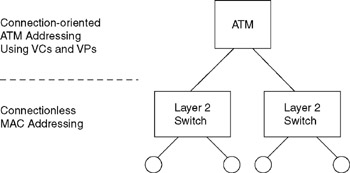
Figure 9.5: ATM versus Legacy LANs
9.2.1 Need for LANE
Prior to the development of LAN Emulation (LANE), network managers who wanted to use ATM as a high-speed backbone to interconnect layer 2-based LANs had to map ATM permanent virtual circuits (PVCs) using VP and VC identifiers to link layer 2 switches through the ATM backbone. Typically, each layer 2 switch would include one or more ATM cards, with both a layer 2 MAC address and an ATM address. The mapping of PVCs from each edge switch through the ATM backbone would provide layer 2 LAN users with the ability to both access ATM resources as well as pass data via an ATM backbone to other layer 2 LAN users, as illustrated in Figure 9.6. Although the mapping of PVCs worked, there were several problems associated with this technique. First, each time the network topology changed, the network would have to have the previously static connections reconfigured, substantially increasing the workload of network managers. Second, to err is human and maintaining correct mappings is a time-consuming process that can be error-prone .
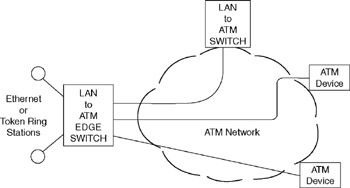
Figure 9.6: Manually Configuring PVCs to Enable LAN-to-ATM Interoperatility
9.2.2 The LAN Emulation Process
Recognizing the deficiencies associated with the manual configuration of PVCs, the ATM Forum introduced an automated technique for mapping layer 2 MAC addresses to ATM addresses. This technique is referred to as LAN Emulation, with LANE Version 1.0 approved during 1995. LANE supports Ethernet to Ethernet via ATM, Ethernet to ATM, Token Ring to Token Ring via ATM, and Token Ring to ATM connectivity. Although FDDI is not directly supported by LANE, you can use a router or switch to bridge FDDI traffic onto a LANE emulation service by first converting its frames to either Ethernet or Token Ring.
9.2.2.1 Components
There are four key components associated with LAN Emulation. Those components include a LAN Emulation client (LEC), a LAN Emulation configuration server (LES), and a broadcast and unknown Server (BUS). Let us first review the general operation of each component prior to examining the emulation process.
9.2.2.2 LAN Emulation Client
The LAN Emulation client (LEC) resides on ATM attached devices, such as a layer 2 switch that has an uplink to an ATM switch. The LEC has two addresses ”an IEEE 48-bit MAC address and a 20-byte ATM address ” and serves as a portal to enable layer 2 LAN connectionless service to be transported via ATM's connection-oriented service. Functions performed by the LEC include address resolution, data forwarding, and the registration of MAC addresses with the LAN Emulation server.
9.2.2.3 LAN Emulation Server
The LAN Emulation server (LES) represents a database repository that contains MAC addresses and corresponding ATM addresses required to reach the MAC address. LECs register their ATM to MAC address translations with the LES. This enables other LECs to send address-resolution requests to the LES to obtain appropriate ATM addresses. Because there can be multiple LECs on an ATM network, a mechanism is required to point the LEC to the correct LES. That mechanism is in the form of a LAN Emulation configuration server (LECS).
9.2.2.4 LAN Emulation Configuration Server
As briefly mentioned earlier, an ATM network can have multiple LESs, each maintaining an independent network within the ATM network. Such networks are referred to as emulated LANs (ELANs) and form domains within the network. To point each LEC to the correct ELAN as well as the LES associated with the ELAN requires the use of a LAN Emulation configuration server (LECS).
The LECS maintains a database of ELANs and the ATM addresses of the LESs that control the ELANs. Thus, a LEC will first query a LECS to determine the address of the appropriate LES to use.
9.2.2.5 Broadcast and Unknown Server
When an LEC attempts to obtain an ATM address, it first checks its cache memory area. If the required address is not in cache, it sends an address-resolution request to the LES, which checks its database. If the desired address at this point in time is unknown, the address-resolution process requires a request containing the MAC address and requesting the ATM address to be broadcast to each LEC on the network. Because ATM is a connection-oriented protocol, it needs a mechanism to issue broadcasts not directly supported by the protocol. That mechanism is provided by the broadcast and unknown server (BUS), which is responsible for distributing broadcasts and multicasts.
Now that we have an appreciation for the components associated with LAN Emulation, we can probe deeper into the manner by which the process occurs. In doing so, we also develop a general model that we can exercise to examine the effect of the LAN Emulation process upon network performance. First we will omit the effect of queuing through LAN switches to develop a basic model concerning LAN Emulation. Once this is accomplished, we then consider the effect of queuing on the LAN Emulation process.
9.2.2.6 Operation and Model Development
To illustrate the LAN Emulation process, let us assume that several Ethernet switches are connected via the use of an ATM backbone, as illustrated in Figure 9.7. When each Ethernet switch is initialized , the LEC on each switch uses either a locally configured ATM address or a fixed address defined by the ATM Forum to locate the LECS. Either method results in the use of a pair of VPIs and VCIs, collectively referred to as a virtual channel connection (VCC). The LEC request shown as number 1 in Figure 9.7 results in the LECS checking its database to determine if the LEC can join the ELAN. Assuming it is permitted to do so, the LECS uses the same VCC to return the ATM address and the name of the LES for the ELAN to the LEC. This is indicated as number 2 in Figure 9.7.
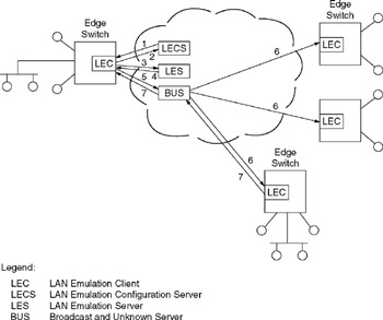
Figure 9.7: The LANE Process
At an ATM operating rate of 155.520 Mbps, one cell of 53 bytes requires:
Therefore, without considering processing delay as the LECS checks its database, the minimum round-trip delay for the LEC to access the LECS and determine the LES to use is 5.45126 10 ˆ’ 6 seconds, or 2 cell times (2C T ). Because the LEC should only require accessing the LECS once to locate its LES, this delay is not cumulative. Once the LECS response is received, the LEC tears down the previously established VCC to the LECS and initiates a new VCC to the LES to exchange information. This VCC represents a bi-directional control VCC that will remain operational as long as the LEC continues to use the LES. Using this VCC, the LEC will also query the LES to determine the ATM address for the BUS. To do so, the LEC transmits an address-resolution request for the broadcast address hex FFFFFF and uses the received ATM address to establish a VCC to the BUS.
Returning to Figure 9.7, numbers 3 and 4 indicate the initial LEC querying of the LES and its response in which it returns the ATM address of the BUS, while number 5 indicates the establishment of a VCC from the LEC to the BUS. Assuming each action is near instantaneous and ignoring processing delays, a minimum of three cell durations must occur until the LEC learns the address of the BUS and establishes a VCC to it. Thus, the additional one-time delay becomes:
This is equivalent to three cells times or 3C T . Now that the LEC knows the LES and BUS to use, let us assume a frame arrives at the switch that needs an ATM address to correctly flow over the ATM network to its destination.
The LEC reads the packet's destination MAC address and examines its forwarding tables in cache memory to determine if it has a corresponding ATM address. If an address is in cache memory, the LEC uses that address and begins segmenting the frame into cells for delivery via the ATM network. The LEC will only find a corresponding ATM address to the destination MAC address if it is currently communicating with the destination ATM device on behalf of another user . Otherwise, the LEC queries the LES to determine if the latter previously learned the ATM address that needs to be resolved. At nearly the same time, the LEC begins transmitting an address-resolution request to the BUS. This overlap cuts down on the time required to resolve the address if the LES cannot provide the address resolution. If the LES has the required address and begins to return it to the LEC, the latter stops transmission to the BUS and uses the address provided by the LES to connect directly to the destination address. When transmitting to the BUS, the LEC uses a LAN Emulation ARP (LE-ARP), in effect broadcasting the known MAC address to each LEC and having the LEC with the correct MAC address respond with its ATM address. Because the BUS performs broadcasting, the LEC sends a request to the BUS. The BUS has a two-way VCC to each LEC that is established during the initialization of each LEC as well as a one-way VCC to each LEC it uses for broadcasts. The BUS uses the one-way VCC to each LEC to broadcast its LE-ARP request and the response from the appropriate LEC then flows through the BUS to the originating LEC.
In continuing our model development, let us assume that P 1 is the probability that the LEC is communicating with the destination ATM device when it receives a LAN frame for forwarding over the network. Then, the probability is 1 ˆ’ P 1 that the LEC must access the LES.
Accessing the LES via a one-cell request requires (1 ˆ’ P 1 ) * 2.7263 10 ˆ’ 6 seconds or (1 ˆ’ P) * C T . Assuming the probability that the LES has learned the desired ATM address is P 2 , then a one-cell response, again assuming no processing time, becomes:
If P 2 is the probability that the LES can resolve the request, then 1 ˆ’ P 2 represents the probability that the LES cannot resolve the request. When this occurs, the LEC sends an LE-ARP to the BUS (number 5 in Figure 9.7), which issues a broadcast to each LEC (number 6 in Figure 9.7), with the LEC having the desired address returning the ATM address (number 7 in Figure 9.7) required to access the destination MAC address. Again assuming instantaneous processing, which while obviously not true, facilitates simplicity, the time required to resolve the ARP becomes:
or (1 ˆ’ P 2 ) * C T * 2, as we will assume a cell must flow in each direction, from the BUS to each LEC and back through the BUS to the LEC. Based on the preceding , the LANE delay components are listed in Table 9.2.
Based on the LANE delay components listed in Table 9.2, the cumulative delay due to the emulation process becomes:
| Activity | Delay |
|---|---|
| LEC-to-LECS access | 2C T |
| LEC-to-LES access and VCC setup to BUS | 3C T |
| LEC access to LES | (1 ˆ’ P 1 )C T |
| LEC ARP request | (1 ˆ’ P 2 )C T * 2 |
| Note: C T = cell time of 2.7263 10 ˆ’ 6 seconds P 1 = probability LEC is communicating with the destination MAC address P 2 = probability LES learned the desired ATM address | |
where N represents the number of addresses that need to be resolved and C T represents the cell transmission time.
When a power failure occurs or switches are first initialized, we have a worst-case condition where P 1 and P 2 are initially 0. In comparison, when ATM switches and the LECs in edge devices have been operational for a period of time, both P 1 and P 2 approach and can reach a value of 1. Thus, let us exercise the preceding equation.
Figure 9.8 illustrates the execution of an EXCEL spreadsheet model for 100, 1000, and 10,000 addresses that require resolution during a backbone initialization procedure or after a power failure. Although the complexity of the emulation process makes it appear that the transmission time associated with the learning of appropriate addresses would be a time-consuming process, the relatively high operating rate of the backbone minimizes the effect of the learning process. In fact, for 10,000 address resolution, the transmission time is eight hundredths of a second for the worst-case condition where each address must be resolved!
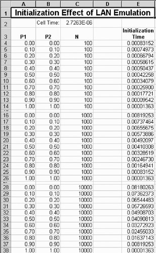
Figure 9.8: The Excel LAN Emulation Initialization Model
Note that the preceding model did not include consideration of the effect of hundreds, thousands, or tens of thousands of MAC layer 2 devices attempting to transmit through an ATM backbone upon recovering from a power failure. In effect, we did not consider the effect of queuing delays that occur when a large number of stations must have MAC addresses resolved via a single uplink. Thus, let us continue our LANE model development by considering the effect of queuing through layer 2 switches as MAC stations contend for access to the ATM backbone.
9.2.3 Queuing Considerations
As previously mentioned, in the preceding LANE model there was one significant omission we will not attempt to address. That omission is the fact that we did not consider the effect of MAC stations becoming active and contending for access to the LE-ARP process via a common port on the layer 2 MAC switch.
Figure 9.9 illustrates the contention of n ports on a layer 2 switch to the 155.52-Mbps ATM uplink port. The number of ports and the operating rate of each port will determine the waiting time in the system which will affect the overall delay in resolving MAC to ATM addresses.
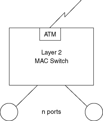
Figure 9.9: When n layer 2 MAC stations become active and require an address resolution, queues develop in the switch which introduce delays
At 155.52 Mbps, the cell slot time is 155.52 10 ˆ’ 6 /53 * 8, or 355792 cells per second. However, one in every 27 cell slots is used for operations, administration, and maintenance (OAM). Thus, the cell slot rate available for actual traffic becomes (26/27) * 366792, or 353208 cells per second. This results in a service time of 1/353208, or 2.831 ¼ s.
Due to possible wide variations concerning the number of LAN ports and their operating rates, let us define some common parameters to use to illustrate the effect of queuing on the LANE process. Let us assume that the switch contains 64 ports, resulting in 63 LAN ports and one ATM uplink. Further assume that each LAN port operates at 10 Mbps and an initial LAN frame containing a destination address that requires resolution results in an ATM cell that begins the emulation process. Then the following question: What is the delay through the switch associated with each address that needs to be resolved?
9.2.3.1 ATM Queuing Parameters
Because ATM provides a constant service time, the formulas used to develop a queuing model are different from the model used earlier in this book. Table 9.3 lists the applicable formulas for a single-phase , single-channel queuing system with Poisson arrivals and constant service rates.
| Utilization | |
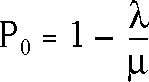
| Probability no activity in system | |
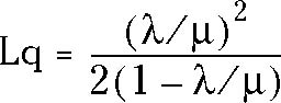
| Length of queue | |
| Length of system | L = Lq = » / ¼ |
| Average waiting time in queue | Wq = Lq/ » |
| Average waiting time in system | W = Wq + 1/ ¼ |

If we assume layer 2 LAN stations are 10-Mbps Ethernet devices, then from Chapter 7 the frame rate in frames per second becomes:
where B is the frame length in bytes. The frame rate represents the maximum arrival rate of frames from one station that upon switch power-up .
If S represents the number of stations, and P 1 and P 2 represent the probability a station is active and has sustained activity, then the frame arrival rate can be expressed as follows :
where B is the frame length in bits.
To facilitate our computations , another LANE spreadsheet model was developed. This model, which computes switch delay time, is shown in Figure 9.10 and is stored at the Web URL previously noted in this book on the file LANE2 in the directory EXCEL. In examining the entries in Figure 9.10, note that the top portion of the model computes a "probabilistic frame arrival rate" based upon a variable frame length and fixed probabilities that the station is active and has a sustained transfer rate. The latter probability recognizes the fact that only a portion of stations are transmitting at anywhere near a sustained level of activity.
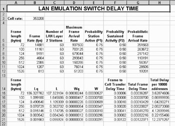
Figure 9.10: The Excel Model LANE2, which Computes the LANE Switch Delay Time
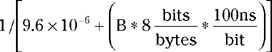
The lower series of computations shown in Figure 9.10 first computes Lq, L, Wq, and W based upon the formulas presented in Table 9.3. Note that W represents the average frame waiting time in the system without considering that a frame must be buffered for the information to be used to form an appropriate cell. Thus, an additional delay time is involved because we must consider frame buffering. This time is computed by multiplying the frame length by 8 to obtain the number of bits in the frame and the result by 100 nanoseconds, which is the bit duration at a data rate of 10 Mbps. Thus, the results of the preceding computations are contained in the column labeled "Frame to Cell Transfer Delay Time." Next, the waiting time in the system is added to the frame to cell delay time to obtain the total frame delay time. The last column in the lower portion of the spreadsheet, which is labeled "Total Delay per 10000 Addresses," shows the frame delay time multiplied by 10,000. This column indicates LAN Emulation delay time attributable to the layer 2 switch. As indicated in Figure 9.10, a maximum delay of approximately 12 seconds could occur under worst-case conditions based upon the prior set of assumptions. Because no two LANE configurations are the same, you will more than likely want to consider varying the frame length, number of stations, and P 1 and P 2 to better reflect your organization's potential or existing use of LANE. When you do so, remember that your assumptions should always result in a probabilistic frame arrival rate less than the cell rate or infinite queues and meaningless results will occur.
While an approximate 12-second delay is not earth shattering, it illustrates the fact that self-healing cannot occur instantaneously under ATM and represents a potential sacrifice to enjoy the fruits of the technology.
In concluding our discussion of LANE, two items deserve mention. First, it should be noted that the LAN Emulation process uses AAL-5, which is the most efficient adaption layer in terms of the use of a 48-byte payload. A second item worth mentioning concerns some limitations of the LANE 1.0 process in addition to the time it takes. Those limitations include the fact that LANE 1.0 only supports a single LES, BUS, and LECS on a single ELAN, which limits its reliability because the failure of one or more servers can result in the entire network becoming inoperative with respect to its address resolution capability. A second major limitation of LANE 1.0 is the fact that it does not distinguish between different types of traffic. Thus, voice could get stuck behind file transfers. Recognizing the preceding problems resulted in the development of LANE 2.0. Under LANE 2.0, multiple LES, BUS, and LECS servers can operate on a single ELAN, increasing reliability and providing redundancy. In addition, LANE 2.0 supports quality of service, to include eight global classes of traffic. This feature enables LANE 2.0 to support constant bit rate (CBR), variable bit rate (VBR), and available bit rate (ABR) traffic in addition to the unspecified bit rate (UBR) traffic supported by LANE 1.0.
EAN: 2147483647
Pages: 111