Lab Objectives
The lab objectives are divided into several sections. Each of the following chapters focuses on one of the sections and completes each section step by step. Before you actually start configuring the lab, it is highly recommended that you read completely all the lab objectives. It is important that you gain a high level understanding of what you will be doing before you start. One suggestion is to redraw the entire lab diagram on a separate piece of paper. Include router names , interfaces (including loopback interfaces), IP addresses, and all routing domain borders. If you are unsure of what your diagram should look like, refer to Appendix A, "Lab Configurations and Diagrams," for an example.
Reread the lab objectives until your diagram contains all devices, IP address, routing domains, and media types. The sections that follow lay out all the lab objectives.
Terminal Server Configuration
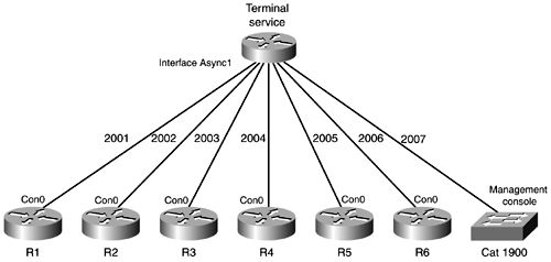
Configure the Cisco 2511 router to be the terminal server for this lab. The terminal server is connected to each device's console port. Port assignments are as follows :
-
R1 2001
-
R2 2002
-
R3 2003
-
R4 2004
-
R5 2005
-
R6 2006
-
Catalyst Switch 2007
NOTE
A terminal server is a router (or other device) that will provide one point of contact for gaining access to all the routers in the lab. Chapter 4 covers the concept of a terminal server and shows how to configure one.
Figure 3-2 depicts the physical connections from the terminal server to the lab routers.
Figure 3-2. Terminal Server Connections
Cisco Catalyst Switch Configuration
-
Configure the switch with a host name of Cat1900.
-
Set the enable password to falcons.
-
Assign the management console an IP address of 192.168.1.3/24 and a default gateway of 192.168.1.10 (the terminal server).
-
Configure ports 1 and 2 (refer to Figure 3-2, if needed) to be in VLAN 1, and name the VLAN vlan-r1r2.
-
Configure port 3 for VLAN 2, and name the VLAN vlan-r2e1.
-
Configure port 4 for VLAN 3, and name the VLAN vlan-r3e0.
-
Configure port 5 for VLAN 4, and name the VLAN vlan-r4e0.
Cisco Router Configuration
Configure all routers to have the following:
-
Host name (that is, host names are to be according to the number R1, R2, R3, and so on).
-
Enable password of falcons.
-
Enable console login with password falcons.
-
Telnet access (vty 0 4), password falcons.
-
No DNS resolution (no domain name lookups).
-
Configure all routers so that the console port will not time out your connection.
-
Configure all routers so that messages from the router to the console screen will not be appended to the command line.
-
Configure all routers to have a description on all active interfaces (except loopback interfaces) stating to which router they are connected and which interface they are using.
-
Configure all routers to show a banner when you log into the console port. In the banner, state which router you are logging into. For example, on Router 1, the banner should read "This is Router 1."
-
Create a host table on all routers using the loopback addresses you just created for each router.
IP Addressing
-
Create loopback interfaces on all routers. Use IP address 192.169. X. X /24 (where X is the router number). So, R1 would have a loopback address of 192.169.1.1/24, R2 would be 192.169.2.2/24, and so on.
Look at the network diagram for IP addressing assignments. Don't forget to look at the netmasks ! The BRI ports on R5 and R6 should use the IP addresses 192.168.200.1/30 and 192.168.200.2/30, respectively.
Routing Information Protocol
Routing Information Protocol (RIP) is a very common routing protocol used in small to medium- size networks. RIP is very important to the CCNA exam, and, in addition, you should have a working knowledge of configuring and troubleshooting routing issues in RIP.
-
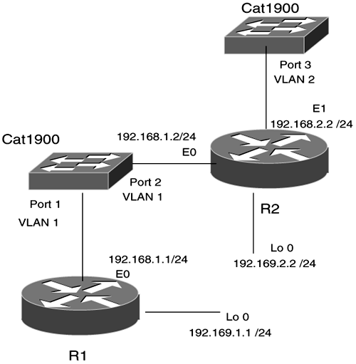
Place R2's loopback 0, E0, and E1 networks into RIP.
-
R1's E0 and loopback 0 networks should be configured for RIP as well.
Figure 3-3 shows the routers that you will be working with in this section.
Figure 3-3. IP RIP Routers
Interior Gateway Routing Protocol
Interior Gateway Routing Protocol (IGRP) is a similar routing protocol to RIP. We have included a section in the lab so that you can see the configuration commands and routing issues with IGRP.
-
Place R3's S1, loopback 0, and R5's To0, loopback 0, and S0 networks into IGRP autonomous system 200.
Figure 3-4 depicts the routers that you will configure in this section.
Figure 3-4. IP IGRP Routers

Enhanced IGRP
Enhanced IGRP (EIGRP) is a very common routing protocol, and you will see it used many networks. It is very important that you understand the configuration process of EIGRP and know some troubleshooting processes for EIGRP. Having a strong working knowledge of EIGRP will be very beneficial in the real world. We have included EIGRP even though the CCNA exam does not cover it in depth.
-
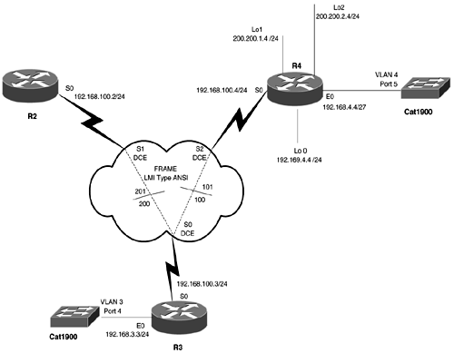
Place R3's S0, R2's S0, R4's S0, and R4's Loopback 0 networks into EIGRP autonomous System 100.
-
Place R3's E0 network and R4's E0 into EIGRP AS 100.
-
Create two loopback interfaces on R4 with the following addresses: loopback 1 = 200.200.1.4/24, loopback 2 = 200.200.2.4/24.
-
Add these two networks into the EIGRP routing domain, and configure R4 so that all other routers see only one route to these two addresses.
Figure 3-5 shows the router setup involved in this section.
Figure 3-5. IP EIGRP Routers
Route Redistribution
Route redistribution is not covered on the CCNA exam, but it is imperative in a working environment that you understand how different routing processes interact. You will see very few networks that do not have some sort of route redistribution occurring at some level.
-
On R2, redistribute RIP into EIGRP and redistribute EIGRP into RIP.
-
On R3, redistribute EIGRP into IGRP and redistribute IGRP into EIGRP.
-
Fix any routing problems that you encounter as you see fit.
All routers should be capable of pinging all interfaces at the end of this section.
ISDN Dial-on-Demand Routing
Dial backup is an important element in most networks. We have included a basic dial-on-demand routing (DDR) situation so that you can see the configuration commands and see how it affects the network logically.
-
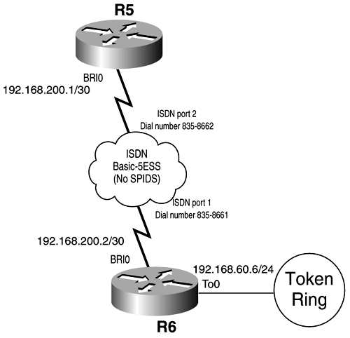
Configure the BRI interfaces on R5 and R6. See Figure 12-2 for ISDN information such as switch type and dial numbers .
-
Use PPP encapsulation.
-
The ISDN link should be active only when IP traffic is present. R6 should call R5. No routing protocols are to be used across the link. Use static routes on R5 and R6, but ensure that workstations on R6's Token Ring network (192.168.60.0) can reach the rest of your network.
-
The link should be brought down after 5 minutes of inactivity.
-
Test R6 connectivity to the rest of your network through Telnet. You must use the host name of each router, which was configured previously (that is, R1, R2, R3, and so on), to initiate the Telnet session.
Figure 3-6 shows the routers involved in configuring DDR.
Figure 3-6. ISDN DDR Routers
Internetwork Packet Exchange
Internetwork Packet Exchange (IPX) is a very common protocol. Although its popularity has diminished, it can be found in many networks. You will find it very helpful to have a good understanding of how IPX is configured on Cisco routers and how the Cisco routers route between IPX networks.
-
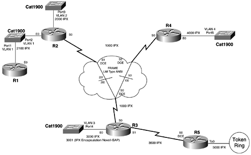
Configure R2's S0, R3's S0, and R4's S1 with IPX network number 1000.
-
Configure R3's S1 and R5's S0 for IPX network number 3500.
-
Configure R5's To0 for IPX network number 5000.
-
Configure R4's E0 for IPX network 4000.
-
Configure R1's E0 and R2's E0 for IPX network 2100.
-
Configure R2's Ethernet 1 for IPX network 2000.
-
Configure R3's E0 with IPX network 3000. Use the default encapsulation type.
-
Configure a secondary IPX network number 3001 on R3's E0. Make the encapsulation Novell SAP.
Figure 3-7 shows the IPX network topology. Note that we will not be configuring ISDN DDR for IPX in this book.
Figure 3-7. IPX Network Topology
IPX EIGRP
-
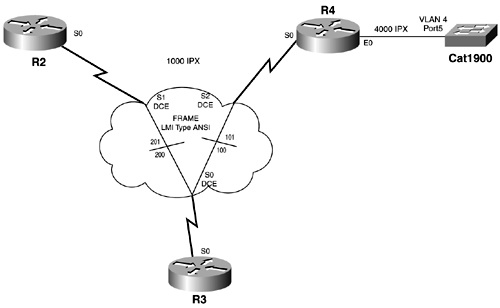
Use IPX EIGRP as the routing protocol for the interfaces in the Frame Relay cloud and R4's E0. Figure 3-8 identifies the router interfaces that will be configured for IPX EIGRP.
Figure 3-8. IPX EIGRP Routers
IPX RIP
-
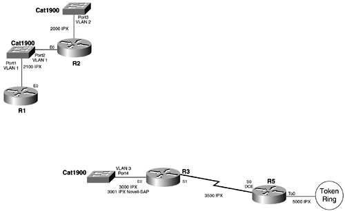
Use IPX RIP for all other router interfaces that are not configured for IPX EIGRP. Figure 3-9 identifies the IPX networks that will be configured for IPX RIP.
Figure 3-9. IPX RIP Routers
IPX Routing Redistribution
-
To make all IPX networks reachable by all IPX routers, redistribute IPX EIGRP and IPX RIP. Make sure that all IPX networks are reachable by using the IPX ping command.
Standard Access Lists
Create a standard outgoing access list and apply it on R2's S0 that fulfills the following requirements:
-
Deny access to users on network 192.168.12.0 to the Frame Relay network. (Assume that this network exists off R1.)
Extended Access Lists
-
Create an extended incoming access list and apply it on R3's S0 that fulfills the following requirements:
-
- Deny HTTP (www) traffic from reaching the Token Ring 1s network.
-
- Deny SMTP traffic from reaching R3's E0 network.
-
- Permit anything else.
-
Cisco Router Operations
The CCNA exam covers some basic router commands and operations. We have included a section that will help you master these commands and give you an understanding of how these commands are applied on routers in a working network environment.
-
Cisco Router Boot Configuration Configure R1 to boot from the TFTP server and then Flash. (Use the Cisco IOS Software image filename igs-j-l.111-18.bin.).
-
Cisco Router IOS Software Backup Backup the Cisco IOS Software image on R1 to the TFTP server 192.168.1.5.
-
Cisco Router IOS Software Upgrade Upgrade the Cisco IOS Software on R1 to image c2500-js-l_112-17.bin from the TFTP server.
-
Cisco Router Configuration Backup Backup the current configurations of R1 to the TFTP server.
-
Cisco Router Configuration Restore Restore the startup config on R1 from the saved image on the TFTP server.
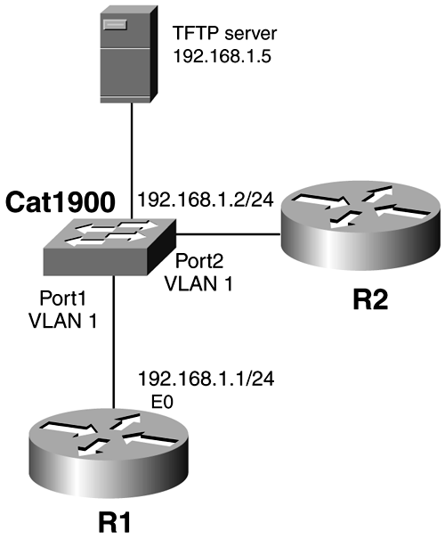
Figure 3-10 gives a depiction of how the TFTP server is incorporated into the network.
Figure 3-10. TFTP Server Topology
| |
| Top |
EAN: 2147483647
Pages: 127