Row Three: Architect s View
Row Three: Architect's View The move during requirements analysis from the business owners ' views of motivation to an architect's view is best described in terms of
Classes of RulesMs. von Halle cites at least seven different schemes for classifying rules today [von Halle, 2002, pp. 2930]. She then consolidates these, eliminating those specific to where they are from, or how they might be manipulated in a computer system to come up with the following scheme:
This is very similar to the scheme described in the first Business Rules Group Paper. In addition to the classifications described here, mandatory constraints may be viewed in two additional categories:
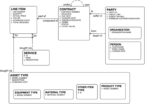
Data integrity constraints can be inferred by studying the data model and looking to common sense. An example would be a rule that the "ship date" in a CONTRACT cannot be before the "order date". A business-oriented constraint is based purely on business policies. For example, a business-oriented constraint might prohibit entry of an ORDER from a customer PARTY if the current CREDIT RATING "value " of the PARTY is below a specified threshold. In some cases the model can help identify rules, but they must still be confirmed by the business community. For example, it may be the case that the dates of occurrences of an entity such as STATUS should not overlap. That is, the "Effective date" of one occurrence must be equal to (or not be before) the "Until date" of the previous occurrence. This seems reasonable, but it should be confirmed. Terms and DefinitionsA term is exactly what it sounds like. It is a word used in the business. More important is the definition of a term, the specification of a meaning for that term as it is used. By defining it, we recognize that it is a term of importance, and we specify exactly what it means. In an analysis project, this may not necessarily be easy, since terms are often not used consistently or coherently in common usage. One of the major assignments of the requirements analysis team is always to recognize what terms are important and to capture coherent and consistent definitions. This is often difficult. Terms and definitions originate as the primary components of the business owners' views of a Column One data model. They are then refined to become the entity types of an architect's Column One data model. Terms are often shown on the data model as entity type names and attribute names . In Figure 8.2, the entity types PARTY, CONTRACT, LINE ITEM , and so forth are all terms. So are the attributes "Contract Number", "Standard Cost", and so on. The definitions are not shown on the drawing, but these must be documented behind the scenes. CASE tools used to produce diagrams typically have a mechanism for capturing the definition of each entity type/term in a repository of some sort . Note, by the way, that there are many terms in an organization that will not show up in an entity/relationship model. These also should be captured and documented. As a product of the requirements analysis project, it is worthwhile to publish a glossary describing the entire vocabulary of the enterprise. Figure 8.2. A Model of Contracts. FactsFacts also reside in the Column One data model. A fact is the linking of terms to produce useful concepts. Facts are what are presented in data models, when entities are related to each other, when attributes apply to entities, and when sub-types are defined. In Figure 8.2, that a PARTY may be a buyer in a CONTRACT is a fact. That "Quantity" is an attribute of LINE ITEM is a fact. That PERSON is a sub-type of (that is, a kind of) PARTY is a fact. In the Business Rules Group's first paper, terms and facts are collectively referred to as "structural assertions". Facts are represented on a data model by explicit relationships, the presence of attributes, and by the super-type/sub-type structures. RulesRules can be either derivations, constraints, or action enabler rules. These are fully the domain of Column Six. DerivationsA derivation is a rule that creates new information from existing information. This may be a mathematical derivation , which is a mathematical calculation. (For example, "Age" is equal to the "System Date" minus the "Birth Date".) Or it may be an inference , which is the drawing of logical conclusions from facts. (For example, if the scheduled "delivery date" has passed and the material hasn't been delivered, this implies that the shipment is "late".) Derivations can be shown on the data model as attributes. The algorithm used to derive the attributes, however, cannot be shown in the model and must be documented in the repository supporting the drawings (along with the definition of the attribute). Some derivations are shown in Figure 8.2, indicated by attribute names in parentheses. Note that in an entity/relationship model, nothing is said about whether the values will be calculated when data are entered or when they are retrieved. It is possible in some database tools to define a "computed attribute", which is stored simply as a formula. Then when the attribute is queried, it is calculated. This can be very expensive, however, if the attribute is queried frequently and it is derived from attributes that are relatively stable. In that case, it would be better to store the computed value. The point is that this is a design decision, which depends on the expected use of each attribute. During analysis, all we are concerned with is recognizing that the derivation takes place. We don't care if it is calculated "going in" or "coming out". A mathematical derivation is a mathematical calculation of an attribute. It may be obtained through several kinds of manipulations of attributes on the models. The first derivation is a simple arithmetic operation on multiple attributes within an entity. An example of this in Figure 8.2 is "(Value)" in LINE ITEM , which is derived for a LINE ITEM by multiplying the "Quantity" ordered in the LINE ITEM by its "Actual Price". The second way to derive an attribute value is to infer a value from a parent to a child entity. An example of this on the model above is "(Standard Cost)" in a LINE ITEM which is the same as the "Standard Cost" in the ASSET TYPE that is bought via that LINE ITEM . A third way to do a calculation is to aggregate a collection of values for occurrences of a child entity to a parent entity. This could be a sum or an average , for example. An example of this is "(Total Value)" in a CONTRACT , which is the sum of occurrences of the "(Value)" attribute in the LINE ITEM occurrences that are part of that CONTRACT. An inference is the drawing of logical conclusions from facts. It is typically evaluated to a value of "true" or "false", although it may have more than two values. In Figure 8.2, an example of an inference is shown by "(Premium Customer Indicator)" in PARTY . This attribute takes a value "True" or "False", based on a predefined threshold for "Credit Limit". ConstraintsA constraint is any restriction applied to data. This is referred to in the first Business Rules Group paper as an action assertion . A constraint affects values that can be assigned to attributes, or indeed even occurrences of entities that can be created in the first place. Examples of constraints that might apply to the model in Figure 8.2 are as follows :
In each case, the assertions must be documented in the repository supporting the drawings, typically in the documentation of the attributes constrained by the rules (in this case, "Total Value", "Due Date", and "Price"). Note that the expression of constraints above is very precise, in terms of the navigation required of the data model. These are Row Three business rules. In Row Two, there are corresponding rules, expressed in more conventional English:
A good example of constraints on the data model are referential integrity constraints. These concern "parent-child" one to many relationships. Specifically, a referential integrity rule defines which circumstance applies if a parent is deleted that participates in a one-to-many relationship:
For the most part, constraints cannot be portrayed on an entity/relationship diagram. Only a few specific kinds of constraints can be expressed in most kinds of entity/relationship models:
The Barker entity/relationship notation provides for one additional constraint: each occurrence of an entity must be related in a specified way to one or another different entity, but not both. In Figure 8.2, this is shown by the arc across two relationships from LINE ITEM. This is saying that each LINE ITEM must be either for one PRODUCT or for one SERVICE , but not both. Other notations, such as information engineering and IDEF1X, cannot show this. Some notations can show additional constraints. The UML, for example, can show some labeled interrelationship constraints. A dashed line between entities ("object classes" in a UML model) may represent not only the "exclusive or" of the Barker notation but also "inclusive or", or any other inter-relationship constraint. Where a constraint cannot be shown in this way, a note can be added to the model, describing it. Object role modeling (ORM) can show many other kinds of constraints, as described below. In addition to simple inter-relationship rules, ORM is more closely based on formal logic and set theory, and constraints involving sets of roles or comparisons between sets of role sequences may also be shown. A constraint may be a mandatory constraint that must be followed or just a guideline that is a recommendation without penalty for not following it. Action Enabler RulesAn action enabler rule is a statement that tests a condition, and upon finding it true, initiates another business event, message, or activity. For example an action enabler rule in Figure 8.2 might be "If a CONTRACT'S "Due date" is greater than two weeks from today, send a backorder notice to the customer PARTY ." Quality CriteriaBusiness Rules Applied includes nine specific criteria to be applied to business rule definitions to ensure that they are sound and coherent [von Halle, 2002, pp. 309310]:
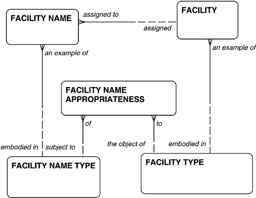
Rule DescriptionsThere are many ways that business rules can be described, and as of this writing, the industry has not established any standards. Some traits are becoming clear, however. Natural LanguageSimple natural language (such as English) is a good choice. This, however, is tricky. For Row Two audiences, this must be clear and uncomplicated. For Row Three audiences, it must be rigorous and tied to the data or object-class model. These may be two very different descriptions. As an example, in the oil industry an oil field consists of "facilities", which are collections of equipment organized for a business purpose. An oil well is a facility, as are a steam generating plant and an oil processing plant. Each facility is an example of a facility type, such as "oil well", " steam -generating plant", or "oil-processing plant". Each of these has one or more names. Each facility name is an example of a facility name type . For example, for regulatory reasons, each well has a "permit name" that is its official name for the regulatory agency, although an oil-processing plant does not. Most facilities also have nicknames, and some kinds of facilities have formal names. The model of this is shown in Figure 8.3. Figure 8.3. Facility Names. One rule can be expressed with the following two expressions:
Object Constraint LanguageThe second version of the rule above is an example of a formal way of describing a business rule. This makes the rule more difficult to understand, but it guarantees that it makes logical sense, and this is the form a programmer will require in order to convert the rule into code. Another formal language for describing rules is part of the UML. The object constraint language is a syntax for describing constraints in an unambiguous language. It is described in a 1999 book by the developers of the language, J. Warmer and Anneke Kleppe. The syntax is intimately associated with UML, however, including its design structures such as interfaces. As such, it is too intricate for inclusion here, but it does show promise as a way of describing rules rigorously, if not clearly. Ronald Ross NotationFor many companies the limitations of data modeling to show constraints has meant that this kind of business rule must be documented in natural language in the repository supporting the model. Not satisfied with documenting rules behind the scenes, Ronald G. Ross has developed a graphical notation for representing constraints. He explains it in his book (originally published in 1994, but updated in 1997), The Business Rule Book . Mr. Ross sees two basic kinds of constraints:
In addition, he has developed a set of 31 standard rule types that he has organized into categories to form what he calls a kind of "periodic table". Each rule type describes the effect of one or more constraining objects ( correspondent in Mr. Ross's language) on a constrained object ( anchor ). A constrained object is an entity, attribute, or relationship in a business rule whose value will be affected by implementation of the rule. A constraining object is an entity, attribute, or relationship in a business rule whose value affects the outcome of the rule. On the left side of Figure 8.4 is an integrity constraint, represented by the arrowhead with the "X" in it. [3] An integrity constraint must be true. The "X", a label for the rule type, means that any occurrence of party must have a value for the attribute "address". Party is the constrained object (anchor), and "address" is the constraining object (correspondent). The "X" is the symbol for one of Mr. Ross' rule types. This rule type is called "must exist". That is, this rule type asserts that each occurrence of PARTY must have a value for the attribute "Address".
Figure 8.4. A Business Rule. On the right side of Figure 8.4 is a condition. In this case, the "X" rule means "test for existence". This says that if an occurrence of PARTY has a value for the attribute "Address", then carry out the next part of the rule. Note that rule elements can indeed be strung together to make complex rules. As in the above case, most rule types may be used as either an integrity constraint or a condition to describe a particular situation. Some rule types, by their nature, can be only one or the other. Note that even if an atomic rule is a condition, it invariably fires off another rule, so both integrity constraints and conditions in this notation qualify as "constraints" as described above by Ms. von Halle. Mr. Ross contends that this list of rule types is atomic and fundamental. While extensive , Mr. Ross does not claim that the list is exhaustive. There are undoubtedly more to be discovered . The list is divided into the following seven categories:
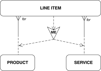
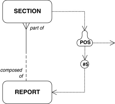
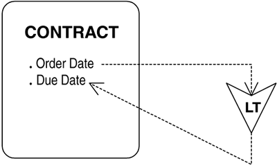
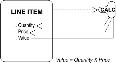
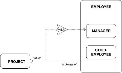
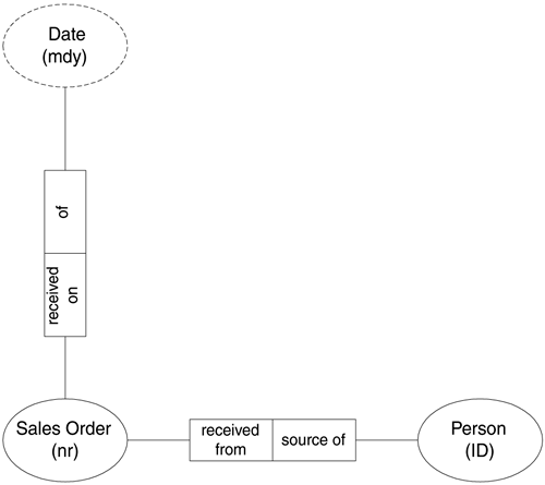
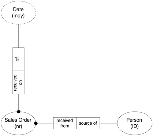
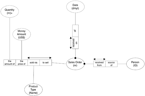
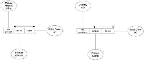
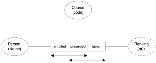
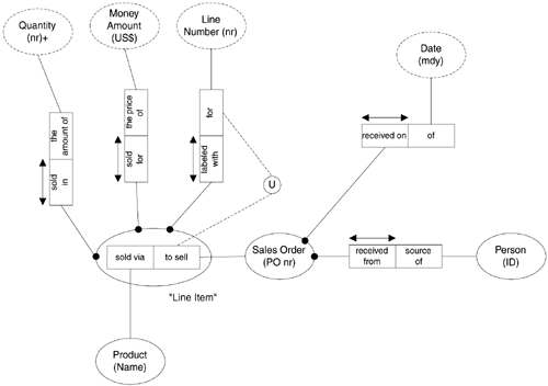
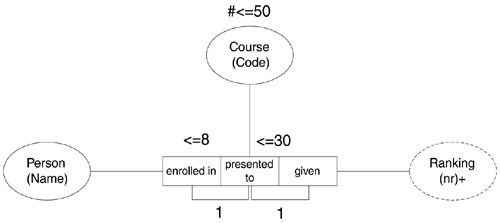
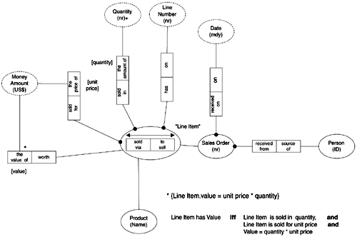
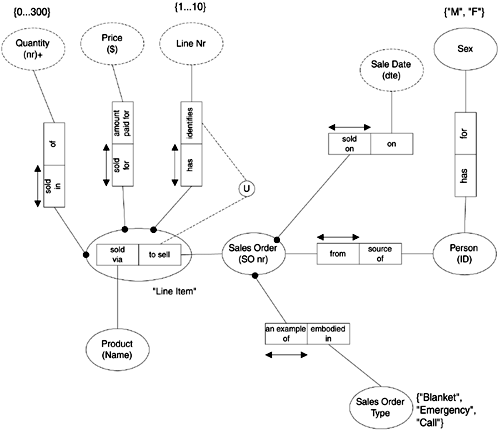
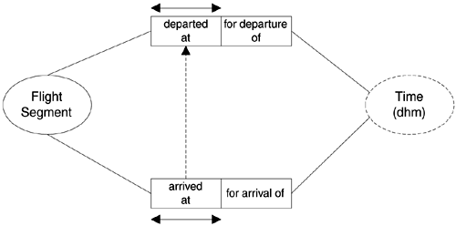
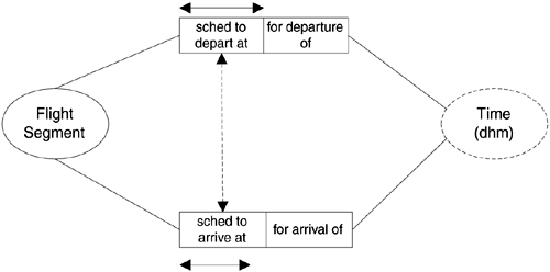
The first five represent "mandatory constraints" in Ms. von Halle's classification scheme described above. "Mathematical evaluators are "derivations" and "projection controllers" are "action enablers" in that scheme. Instance VerifiersIn Figure 8.4 the X is an example of the instance verifier "Mandatory". A Mandatory rule either asserts that something must exist, or it is a test of whether or not something exists. Another kind of instance verifier is "Limit", which prescribes a number of occurrences of an entity. For example, a CONTRACT may be limited to six LINE ITEMS. Type VerifiersFigure 8.5 shows a kind of type verifier , an example of the second category of constraints. This one is "Mutually Exclusive" (ME). (This constraint can, in fact, be represented in some entity/relationship notations.) Here, each LINE ITEM must be either for one PRODUCT , or for one SERVICE. Other type verifiers include "Mutually Inclusive", "Mutually Prohibited", and "Mutual". Figure 8.5. Type Verifiers. Position VerifiersFigure 8.6 shows an example of a position verifier . This one is called "Position" (POS). It is an example of a rule that takes an argument, which is the particular position in sequence being sought. In this case, the rule means that if the SECTION in question is the fifth in a REPORT , then.... Figure 8.6. Position Verifiers. Because by definition this rule type refers only to one of the occurrences of SECTION, it must always be a condition, not an integrity constraint. You cannot assert that every SECTION must be fifth in a REPORT. Other position verifiers include "Low" and "High" (the SECTION that is the lowest or highest in sequence invokes the next rule), and "Old" and "New" (the SECTION that is oldest or newest invokes the next rule). The position verifier "Chron" takes an argument that is the object's position in chronological order. For example, the rule may fire if the object is the third to take place. Functional VerifiersFigure 8.7 shows two examples of a kind of functional verifier . A functional verifier is a rule about an occurrence of an entity, relative to other occurrences in the entity. In this example, the "Unique" rule addresses whether occurrences of RENTAL AGREEMENT have unique "Effective Dates". In the integrity constraint on the left, the "Effective Date" of each occurrence of RENTAL AGREEMENT must be unique. In the condition on the right, the argument "not" makes the rule mean, "If the 'Effective Date' of an occurrence of RENTAL AGREEMENT is not unique, then...." Figure 8.7. Functional Verifiers. Other functional verifiers include "Fluctuating", "Ascending", "Descending", "Nonrenewable", and the nonspecific "Functional". Comparative EvaluatorsA comparative evaluator , as its name implies, compares two elements in the data model. In the "Less-Than" integrity constraint shown in Figure 8.8, the "Order Date" must be less than the "Due Date". Other comparative evaluators include "Equal-To", "Not-Equal-To", "Greater-Than", "Greater-Than-or-Equal-To", and "Less-Than-Or-Equal-To". Figure 8.8. Comparative Evaluators. Mathematical EvaluatorsA mathematical evaluator derives an attribute from other attribute values. In Figure 8.9, "Value" is calculated from "Quantity" and "Price" according to the formula "Value = Quantity x Price". The solid line points to the result, and the dashed lines point to components of that result. There are numerous other kinds of mathematical evaluators, such as "Sum", "Add", "Subtract", and the like. Figure 8.9. Mathematical Evaluators. Projection ControllersWhere other kinds of rules restrain values, projection controllers cause things to happen. A value may "Enable" another value or another rule, "Copy" the value of the anchor to a correspondent, or cause an action to be "Executed". In the latter case, the notation reaches beyond the data model to represent the function executed. Here a Column Six business rule is invoking a Column Two activity. Figure 8.10 shows an example of an "Enabler". In this case, being in charge of a PROJECT makes an EMPLOYEE a MANAGER. Figure 8.10. Projection Controllers. The examples here are simple atomic rules. Real rules are combinations of these. Complex configurations are possible, and it is also possible to create templates reflecting patterns that can be reused. Object-Role Modeling (ORM)Object-role modeling is a modeling technique that views the world simply in terms of objects playing roles ( parts in relationships). Originally developed in Europe in the early 1970s, and once going under the name of "NIAM", it has been significantly extended over the years by researchers in Europe, Australia, and the United States. It is described in detail in Appendix B. It is significant in the business rules world because it provides a means of describing many inter-attribute and inter-entity rules. Entity Types, Attributes, and RelationshipsEntity types are represented in ORM as simple ellipses or circles. As in entity/relationship (e/r) diagrams, entity types are related to each other via named relationships. Each relationship consists of one role for each participant in it. (There can be more than two entities participating in a relationship.) The objects in an ORM diagram are entity types and value types. An entity type is the same as we have seen beforea thing of significance to the organization. A value type is a classification of value, similar to a domain in e/r modeling. Examples include " monetary amount", "date", and so forth Entity types and value types are the "objects" in object role modeling. Essentially, a fact is simply an object's playing a role. A role is the half of a relationship reading in one direction. Two or more entity types playing roles with respect to each other constitute a relationship In Figure 8.11, Sales Order and Person are real-world entity types, while Date is a value type. (Solid ellipses denote entity types, while dashed ellipses denote value types.) When a value type serves as an identifier (as in the Person "ID" and the Sales Order "nr"), it is shown inside the ellipse as a label of the entity type, indicating that it is a unique identifier. In a value type, its data type (such as "mdy", meaning "month/day/year") is shown below the value name. Figure 8.11. An Object Role Model. There are no rules about role names, beyond the fact that they should be readable as sentences. Given that, your author has taken the liberty of constraining names to a modification of the form used in the Barker e/r notation. In the example, each Sales Order is received from a Person, and each Person is the source of a Sales Order. A Sales Order also plays a role with respect to the value type Date. Specifically, each Sales Order is received on a Date, and each Date is of a Sales Order. These relationships are further described in the following sections. Note that the relational concept of "attribute" doesn't really apply here. The "Receipt date" that would be an attribute of Sales Order here is represented by the received on role. About ConstraintsORM is much more versatile than other modeling languages in its ability to represent business rules and constraints. The following sections show how this is so. ORM certainly does not represent all possible constraints on data, but it is able to represent a large proportion of them. Mandatory RolesFirst, like e/r modeling, ORM has the ability to show that a role is mandatory. In ORM, this is shown with a dark dot between the object and the role involved. In Figure 8.12, the role from Sales Order to Person is mandatory. Each Sales Order must be received from one Person. The same symbol is also used to show that an attribute is mandatory. In the figure, each Sales Order must be received on a Date. Figure 8.12. Mandatory Roles. UniquenessThe notion of whether an occurrence of an entity type is associated with one entity type or multiple occurrences of an entity type is known in the e/r modeling world as "cardinality". Usually this is shown by the absence or presence of a crow's foot or asterisk next to the entity type which is singular or multiple. In ORM, the question is asked differently. It is not, "How many occurrences of another entity type are objects of this role?" Rather it is, "How many times may the same entity instance play this role (at any given state of the database)?" That is, "May an object instance playing that role do so multiple times?" In Figure 8.13 each Sales Order has a single occurrence of the role "received from" a Person. That is, each Sales Order must be received from one and only one Person. This is shown by the horizontal arrow over the "received from" role box. "Source of", the Person role, on the other hand is not unique. There is no horizontal arrow. This means that a Person may be source of a Sales Order multiple times. Figure 8.13. Uniqueness. Figure 8.13 also shows that relationships in ORM do not have to be binary. Arity is the number of entity types permitted to participate in a relationship. In entity/relationship modeling, relationships can only have an arity of 2. (This means that each relationship can only be between two entity types.) In ORM, relationships can have an arity of more than 2. In Figure 8.13, Sales Order, Product, Quantity, and Money amount come together in a single relationship. In this case, there are two entities and two value types, but there could easily also be additional entities or value types in the relationship. Among other things, this example shows that this concept of uniqueness turns out to be much more versatile than the simple concept of cardinality. For example, a horizontal arrow is across both the "sold via" and "to sell" roles in the relationship between Sales Order and Product. What this means is that it is only the combination of a Sales Order's selling and a Product's being sold that is unique. A Sales Order may be to sell one or more Products, and a Product may be sold via one or more Sales Orders. This is the ORM version of the many-to-many relationship. It is not necessary to create an intersect entity. Because the arity of the relationship is not limited to two, attributes of the intersection (such as Price and Quantity, in this case) can simply be added with more roles. The model in Figure 8.13 has an interesting problem in ORM terms: The facts shown are not elementary . The relationship between Sales Order and Product appears to be analogous to the way one would set up a line item table. There are references to the Sales Order and to the Product, plus references to two attributes of the relationship, "Price" and "Quantity". In fact, the model in Figure 8.13 can be made more elementary by converting it to the two models in Figure 8.14. Figure 8.14. Elementary Facts. The rule is that there can be no more than one role more than the roles which determine uniqueness. Neither "the amount of" nor "the price of" participates in the uniqueness constraint on the relationships. Only one such nonunique role is permitted. In relational terms, this means that no table can have more than one non-key attribute. It seems like a strict rule, but it does guarantee that you are looking at the most atomic information possible. Figure 8.14 shows the elementary facts that result from implementing this rule. The concept of uniqueness applies equally to entities and attributes. In Figure 8.15, people take courses, and each person receives a ranking. Only one person can be first, second, and so forth in a course. In the model, then, each combination of Person and Course is unique. That is, there must be only one Ranking for each Person/Course combination. This is shown by the upper arrow across "enrolled" and "presented". But it is also true that in a Course, given a Ranking, there is only one Person occupying that rank. Thus, a second uniqueness bar represents the fact that each Course/Ranking combination is also unique. Figure 8.15. More on Uniqueness. Note that, with more than two roles in a relationship, the Barker naming convention breaks down, since the resulting sentence has more than one object. You cannot say "each COURSE may be presented to one PERSON and one RANKING ". So, the roll names are now simply "enrolled" and "presented". Objectified RelationshipsWhile it is not necessary to resolve many-to-many relationships in ORM, it is sometimes useful to do so. Figure 8.16 shows the creation of "Line Item" from the intersection between the "sold via" and "to sell" roles. Line Item in this case is an objectified relationship and behaves in all respects like an entity type. This then makes it possible to apply the additional roles for Quantity and Price as attributes of this new entity type. We also add a new attribute Line Number. Figure 8.16. Objectified Relationships. Notice the circled "U" symbol connecting the Line Number "for" role with the Sales Order "to sell" role. This means that that combination of roles is unique. This is called an external uniqueness identifier. This means that a given Sales Order plus a given line number is a unique combination. Note that adding the Line Number role as part of the identifier of the "Line Item" relationship allows the combination of Sales Order and Product to be not unique, if we choose to make it so. This allows the same product to appear twice on one Sales Order. If we don't want that to happen, we must add back the double-headed arrow that was in the previous drawing. Notice also that now the "attributes" of Line Item are shown as separate relationships to value types. Therefore we need not limit ourselves to one non-key attribute. Each relationship is already an atomic fact. Occurrence FrequencyThe notation for "one or more" in ORM is simply the absence of a uniqueness constraint. For example, in Figure 8.16, each Person may be source of one or more Sales Orders. Back in Figure 8.15, each Ranking may be given to any number of Course/Person combinations. Similarly, each Person may be enrolled in one or more Courses, each with its own Ranking, and each Course may be given to one or more People. A cardinality constraint may be specified by adding a number to the role. For example, "<=8" could be placed next to the "enrolled in" role to designate that each Person may be enrolled in no more than 8 Courses. This is shown in Figure 8.17. Similarly, each course is restricted to no more than 30 People, so "<=30" appears next to the "presented" role. More complex rules could also be specified for the "enrolled in" role, such as "2... 8" or "3, 5, 8" for requiring at least 2 but allowing no more than 8, or for insisting on exactly either 3, 5, or 8 courses. Figure 8.17. Occurrence Frequency. Unlike with e/r modeling, you can also specify the cardinality of an object itself. An object cardinality constraint is a number that defines the maximum or minimum number of occurrences that are possible for a given object at a given time. In the example in the figure, no more than 50 courses may be offered at one time. The octothorp (#) means that the count of objects can be no greater than 50. Using the number "1" with a role or roles is equivalent to adding the double-headed arrow uniqueness constraint across that role. This is also shown in Figure 8.17, showing that "enrolled in" and "presented to" constitute one uniqueness constraint, and "presented to" and "give" are another. DerivationsOne important kind of business rule is the derivation. With the ORM notation you may or may not choose to show derived values graphically on the diagram, but in either case, ORM accommodates defining them in the technique. Derived attributes are not shown as value types, but they are shown on diagrams as being formally defined in terms of other attributes. In Figure 8.18, for example, each Line Item has explicit roles of [Quantity], which is the amount of the Line Item, and [Unit Price], which is the price of the Line Item. Note the addition of rolenames for the roles shown in square brackets. "Unit Price" is the name of the "the price of" role. [Value] is the name of the "the value of" role, and describes the complete value of the lineUnit Price times Quantity. Figure 8.18. Derivations. The formula for Value is displayed separately, as text. Specifically, Line Item.Value = Line Item.Unit price * Line Item.Quantity. This is an informal specification. The formal definition is shown on the diagram below the informal one. In the formal definition, "iff" is from logic and means "if and only if", which is to say that the left side of the expression is identical in meaning to the right side. Note that this example shows how value types really do represent domains and not attributes. Both "the value of" and "the price of" roles are played by the value type (domain) Money Amount, which is expressed in United States dollars. Value ConstraintsOne constraint that is very common has to do with the values that an attribute can take. In e/r modeling, if the list is discrete, this is often addressed with a "Type" entity, or with a domain. If the attribute is continuous (accepting any real number), minimum and maximum values may be set in a domain definition. In either case, the model doesn't actually show the legal values. Since these domains constitute a significant element in the configuration of the final system, it would be good if they were more visible. In ORM they are. A value constraint is a list of possible values for an attribute. In Figure 8.19 we have added some new entities. First we determined that each Person has a Sex. The values available for "Sex" are "M" and "F", as shown in the brackets. For purposes of this exercise, we have asserted that only 10 line items per order are possible. This is done indirectly by saying that Line Number can have only the values 1 through 10. Since the uniqueness constraint says that a Line Item can have only one Line Number, then that effectively limits us to 10 Line Items. In addition, because of the nature of the products we are selling (undisclosed here), the Quantity that appears on a single line item can be no larger than 300 units. Figure 8.19. Value Constraints. Another addition to the model is Sales Order Type. ORM is not clear as to whether it is an attribute of Sales Order or another entity type. As it happens, it doesn't matter. If the only thing you need is the name of the Sales Order Type, it can simply be an attributeconstrained by the list of available values. (It is usually implemented in a relational database as a separate table, with one row for each of the legal values, but that doesn't concern us here.) In this case, a Sales Order can be an example of a "Blanket" order, an "Emergency" order, or a "Call" against a blanket order. Set ConstraintsSubsetsFigure 8.20 shows part of the model of an airline's flight schedule. This part describes the actual departure and arrival of a Flight Segment, where a Flight Segment is defined as a single trip, without stops, between two airports. Continental Airlines flight 635, for example, departed Los Angeles for Houston at 2:10 p.m. on August 17, 2001, and it arrived at 7:30 p.m. Both the departure and arrival roles are examples of the value type Time, expressed in "day, hour , minute". Figure 8.20. Subset Constraint. There is a rule here that says that a plane may not arrive if it has not departed. That is, the set of Flight Segments that show Arrival Times have to be a subset of the Flight Segments that show Departure Times. This is shown on the diagram by the dashed arrow. It shows that a Flight Segment may have departed without arriving yet, but it cannot have arrived if it has not departed. Note that both these roles are optional. A Flight Segment may not have taken off at all. Set ConstraintsJoin Subset ConstraintIn an example described previously, an oil field consists of "facilities", which are collections of equipment organized for a business purpose. An oil well is a Facility, as is a steam generating plant, or an oil processing plant. Each Facility is an example of a Facility Type, such as "oil well", "steam generating plant", or "oil processing plant". Each of these has one or more names. Each Facility Name is an example of a Facility Name Type. For example, for regulatory reasons, each well has a "permit name" that is its official name for the regulatory agency, although an oil processing plant does not. Most facilities also have nicknames, and some kinds of facilities have formal names. On page 305, we saw the rule
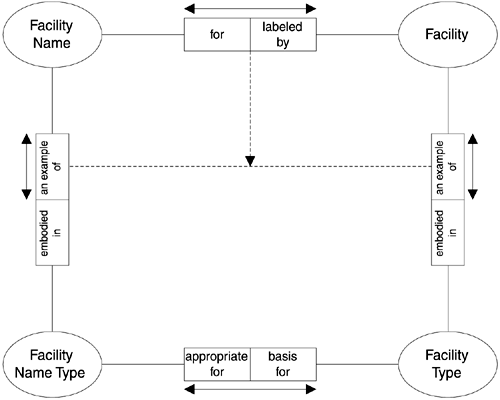
Note that, while the e/r model in Figure 8.3 has the entity type FACILITY NAME APPROPRIATENESS to support the rule, the rule itself cannot be represented on that diagram. The ORM version of this rule is that
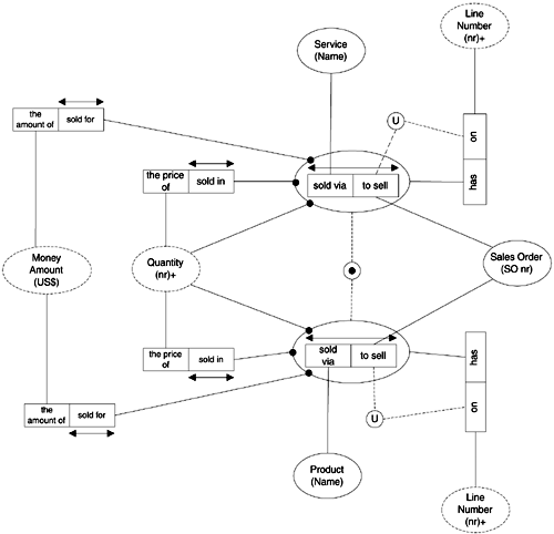
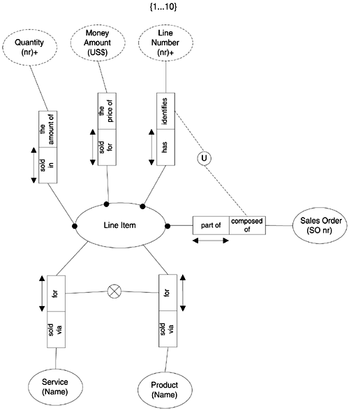
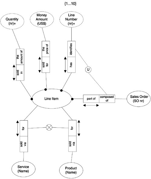
This is represented in Figure 8.21. The notation that describes this rule has two parts. First, the line between the two "an example of" roles is called a conceptual join path . A conceptual join path is a connection between two relationships suggesting that they are in fact related to each other. This asserts a complete fact that each Facility Name is an example of one Facility Name Type that is appropriate for a Facility Type that is embodied in a Facility. Going in the other direction, each Facility is an example of one Facility Type that is the basis for a Facility Name Type that is embodied in a Facility Name. Figure 8.21. Join Subset Constraint. The second part of the rule, then, is the assertion that the set of facts expressed by the "for"/"labeled by" relationship must be a subset of the set of facts expressed by the FacilityName/Facility projection to the conceptual join path. Note that in Figure 8.21 the subset constraint was applied to two roles. Here it is to the entire relationship between two role sequences. Set ConstraintsEqualityFigure 8.22 shows a variation on the subset constraint shown above. In this example we see scheduled flights , rather than actual ones, so for each occurrence of a scheduled departure time there must be a scheduled arrival time as well, and vice versa. This equality constraint is shown by the double-headed dashed arrow. Figure 8.22. Equality Constraint. Set ConstraintsExclusionGetting back to our Sales Order model, we can extend it to permit purchasing services as well as products. In Figure 8.23, a Sales Order must be either to sell a Service, or to sell a Product, or both. The relationships involved are circled, and a line is drawn between them. The solid dot in the circle on that line is the same "mandatory" indicator we saw for relationships and entity types, but here it is saying that the pair is mandatory, although either or both elements could be selected. Because both may apply, this is called an inclusive or constraint. Figure 8.23. Inclusive Or. To use our sales example to demonstrate the next constraint, we must promote the objectified relationship Line Item to a real entity. This allows us to discuss the alternative things a Line Item might be about. Figure 8.24 makes the assertion that a Line Item may be for either a Product or a Service, but not both. The "X" in the circle means "exclusive or". Because there is no solid dot, it also means that the Line Item could be for neither a Product nor a Service. Figure 8.24. Exclusive OrVersion 1. This introduces one flaw in this model. If we want to require that a line item must be for either a Product or a Service, we need the symbol shown in Figure 8.25. This is the "X" with the mandatory dot over it. Figure 8.25. Exclusive OrVersion 2. To summarize, there are two forms of inclusive or :
And there are two forms of exclusive or :
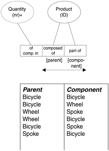
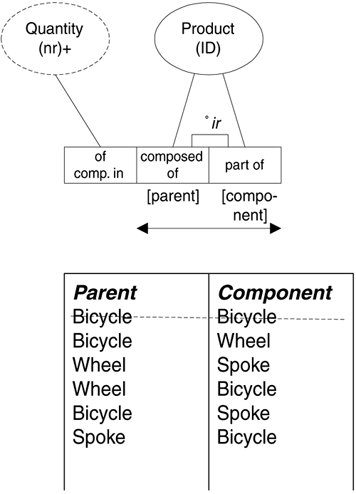
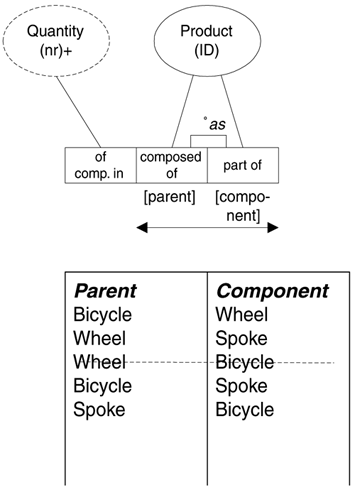
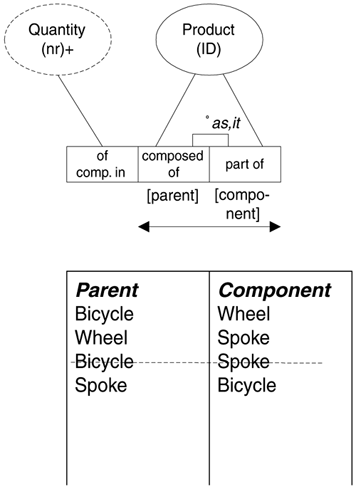
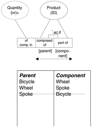
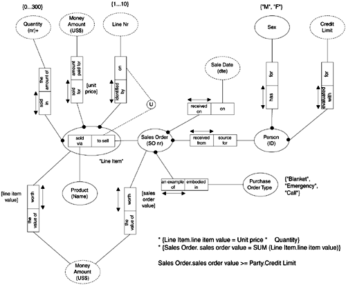
Ring ConstraintsWhen occurrences of an entity are related to other occurrences of the same entity, this is a ring in ORM. It is common in the description of manufacturing product structures, but it also appears when describing such things as logistics networks and other inter-entity type relationships. Figure 8.26 shows a product structure, where a Product may be composed of one or more other Products, and a Product may be a component of one or more other Products. The Quantity value tells how many of the component are required to create one of the parent. Figure 8.26. A Ring. This structure can be represented easily enough in an e/r diagram, but it is not possible to describe a series of constraints that might apply. The table below the diagram shows some possible values for the structure. Given the drawing as it is, these are all legal values. Upon examination, however, it is apparent that some of these combinations should not be legal. The first problem is that it should not be possible for a "Bicycle" to be a component of a "Bicycle". This violates our understanding of the nature of things in the world. The ring should not be what is called reflexive . It should be irreflexive . Figure 8.27 shows this constraint added. It is in the form of the notation o ir . Note that the designation applies to the set of both roles. Figure 8.27. Irreflexive. There are still some problems with the sample data. Note that a Bicycle can contain a Wheel, and a Wheel can contain a Bicycle. In the world, it is unlikely that this symmetry is the case, so we need a constraint that will prevent it. The constraint ( o as ) in Figure 8.28 makes it asymmetric . Figure 8.28. Asymmetric. Note that if it is not permitted to have a pair that is another pair in reverse, that includes the situation where the pair is itself in reverse. That is, if the relationship is asymmetric, it is also irreflexive. The o ir is unnecessary. Another problem with our sample data is that a "Bicycle" consists of a "Wheel", a "Wheel" consists of a "Spoke", and a "Bicycle" also consists of a "Spoke". While the construction of some products may allow such transitiveness , we are going to say for purposes of this exercise that it isn't allowed. The constraint " o it " shows the relationship to be intransitive in Figure 8.29. Figure 8.29. Intransitive. The remaining problem with the sample data in our example is that a "Bicycle" is composed of "Wheels", and a "Wheel" is composed of "Spokes", but a "Spoke" is composed of "Bicycles". This kind of loop is not permitted in the real world, so our model must reflect this. This is a more general case of the asymmetry constraint shown in Figure 8.28. This is called acyclic . It is added as a constraint in Figure 8.30. Figure 8.30. Acyclic. Other ConstraintsThis section has described some of the constraints that can be expressed directly with the ORM notation. Like all notations, ORM cannot describe all of the constraints that might apply. Supplementing the notation with formal predicate logic statements, however, allows all to be expressed overall. For example, in Figure 8.31 we are interested in a little more information about the Person at the other end of the Sales Order transaction. Specifically, each Person must be evaluated with a Credit Limit. By adding another derived value, "sales order value", computed as the sum of the "line item values" of all associated Line Items, we can express the rule that the total value of the Sales Order may not be greater than the credit limit of the Person doing the buying. Figure 8.31. Credit Limit. Notice in this model that the value type "Money Amount" is used both to mean line item value and sales order value. This is the difference between an ORM value type and an e/r model's attribute. Here a value type plays the role of an attribute, in this case more than once. In e/r modeling, a domain may be shared by different attributes, but that does not show on the model. Rule PatternsMs. von Halle proposes the use of what she calls rule patterns . Predicated on the realization that rules (as opposed to terms and facts) are nearly always conditional, she argues for setting up rule-pattern tables, where the columns are:
Such tables can then be used to identify rule-integrity problems. The rule just described above (The FACILITY NAME chosen must be of a FACILITY NAME TYPE that is appropriate for the FACILITY TYPE involved), then, can be represented by the rule pattern in Table 8.1. Table 8.1. Rule Patterns
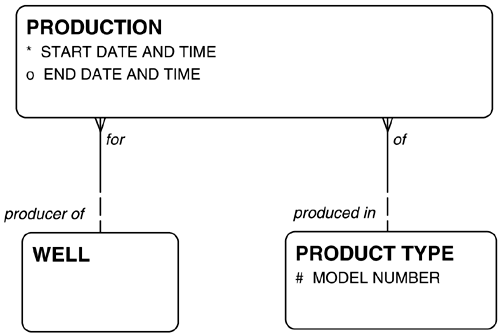
This means that if an occurrence of FACILITY NAME APPROPRIATENESS exists that links a particular FACILITY NAME TYPE with a particular FACILITY TYPE , then it is permitted for a FACILITY NAME (of the specified FACILITY NAME TYPE ) to be assigned to a FACILITY (of the specified FACILITY TYPE ). Another set of rules apply to the model in Figure 8.32. Here, PRODUCTION is the fact that a WELL is producing a particular PRODUCT TYPE at a given point in time. The rules are that (a) a WELL may be producer of one or more PRODUCTIONS of different PRODUCT TYPES , but (b) a WELL may be producer of only one PRODUCTION at a time. That is, the "Start date and time" of a PRODUCTION must be after the "End date and time" of prior PRODUCTIONS, and the "End date and time", if any, must be before any subsequent PRODUCTIONS. Only one PRODUCTION may have a null "End date and time". That is, a well may produce both crude oil and natural gas, but not at the same time. Figure 8.32. Production. The rule pattern for this situation is shown in Table 8.2. Table 8.2. Production Rules
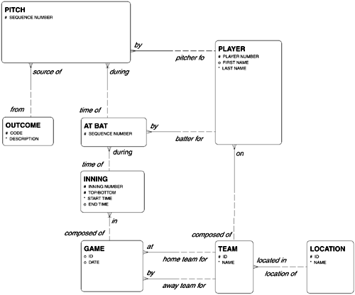
The table shows all permutations of placements of start and end dates of two occurrences of the PRODUCTION entity type. For each permutation, the rightmost column says whether it is allowed. In some cases, the value in one column dictates the value of another column. In R2 and R3, for example, if the START DATE of occurrence 1 is after the START DATE of occurrence 2, then the END DATE of occurrence 1 must be after the START DATE of occurrence 2. Similarly, in R4 and R5, if the START DATE of occurrence 1 is not after the START DATE of occurrence 2, then the END DATE of occurrence 1 cannot be after the END DATE of occurrence 2. In R2, the START DATE of the first occurrence is after both the START and END DATES of the second occurrence, so it is allowed. In R3, the START DATE of the first occurrence is after the START DATE of the second OCCURRENCE , but before its END DATE , so it is not allowed. In R4, the start date of the first is before the START DATE of the second occurrence, but its END DATE is AFTER the START DATE of the second occurrence, so it is not permitted, In R5, both the START DATE and the END DATE of occurrence 1 are before the start date of occurrence 2, so it is allowed. Business Rule PatternsCASEtech, Inc.Peter Brenner, Ed Campbell, and David Wendelken of CASEtech, Inc. have developed an extensive catalogue of business rule patterns. Unlike Ms. von Halle's patterns or the other notation and classification schemes described above, these are described in simple English, and they are accompanied by PL/SQL subroutines. They are intended to be captured in a tool, so that a particular rule can be implemented inheriting characteristics of the pattern. The patterns they have collected correspond to many of Ron Ross's and ORM's examples described above. The approach here differs from the others, however, in that one purpose of the patterns is to provide a vocabulary with which to describe business rules to the public at large. As described earlier, it is often difficult to describe a rule in a style that is both rigorous enough to be implementable and simple enough to be clearly understood . Patterns can be taught, however, and then it is simply a matter of referring to them. For example, two sets of relationships are "cousins" if they connect the same two entity types. The "cousin" rule states that "If two different relationship paths from an entity type back to the same ' ancestor ' entity type exist, the two paths from any occurrence in this entity type must be traced back to the same occurrence in the ancestor entity type" [based on Brenner, et. al. 2002, p. 7]. The "no cousin" rule states that the two paths from any occurrence must be traced to different occurrences in the ancestor entity type. For example, Figure 8.33 shows that there are two paths from PITCH to PLAYER . Each PITCH must be by one PLAYER , and it must be during one AT BAT which in turn must be by one PLAYER . In this case, the "no cousin" rule pattern is invoked: it is not permitted for a player to pitch to himself. Figure 8.33. "Cousins" and Rules. Figure 8.33 also shows another cousin situation in the multiple paths from AT BAT to TEAM . In this case the "cousin" rule is invoked. The PLAYER who is the batter for an AT BAT must be in fact on a TEAM that is either the home team for or the away team for the GAME with the INNING that is the time of that AT BAT . Other patterns include:
| ||||||||||||||||||||||||||||||||||||||||||||
| | |
| Team-Fly |
| Top |
EAN: 2147483647
Pages: 129

